M3plus_OperationManual_e.pdf - 第20页
Table of Contents 1. Main unit . . . . . . . . . . . . . . . . . . . . . . . . . . . . . . . . . . . . . . 1-1 2. Operation panel and data input units . . . . . . . . . . . . . . . 1-3 2.1 Oper ation panel buttons . . . …
xii
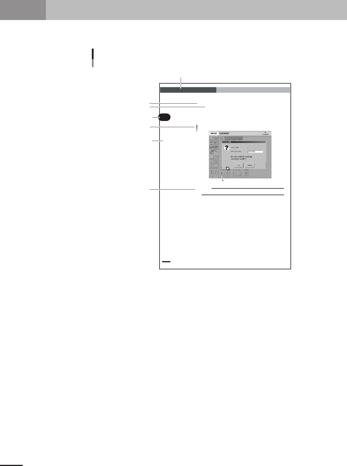
4. Page layout
The description below shows a typical page layout used in this manual.
2 -14
2
Basic oper
ation
3. Starting and stopping the machine
3.4.1 Conveyor width
First adjust the conveyor width to match the PCB width to be produced.
1
Select the PCB data.
See the description of "2.2 Selecting the PCB data" in chapter 3.
2
Open the [Unit]-[Conveyor] tab screen.
3
Press the [Width] button.
The Conveyor Width dialog box appears. Check the conveyor width and press th e
[OK] button. The conveyor rail automatically changes to the specified width.
[Width] button
Conveyor Width dialog box
27311-5E-20
c
CAUTION
When adjusting the conveyor rail width, make sure that the conveyor rails do not make contact
with push-up pins attached on the push-up plate.
Illustration or table title
Note, Caution or Warning
Section in chapter
Step
Chapter title
Chapter number
Sub step or description of step
Typical page layout
23002-5E-20
Step
This describes the procedure for each operation.
Substep or description of step
This provides detailed information on the steps in each procedure.
Illustration or table title
This is the title of the illustration or table and appears at the upper left.
Note, Caution or Warning
These are explained in the "Safety and warranty" introductory section.

Table of Contents
1. Main unit . . . . . . . . . . . . . . . . . . . . . . . . . . . . . . . . . . . . . . 1-1
2. Operation panel and data input units . . . . . . . . . . . . . . . 1-3
2.1 Operation panel buttons . . . . . . . . . . . . . . . . . . . . . . . . . . . . . . . 1-4
2.2 Keyboard and mouse . . . . . . . . . . . . . . . . . . . . . . . . . . . . . . . . . . 1-5
3. Head assembly . . . . . . . . . . . . . . . . . . . . . . . . . . . . . . . . . 1-6
3.1 Component pickup/mount head . . . . . . . . . . . . . . . . . . . . . . . . . 1-6
3.2 Nozzle types . . . . . . . . . . . . . . . . . . . . . . . . . . . . . . . . . . . . . . . . 1-6
3.3 Nozzle station (option) . . . . . . . . . . . . . . . . . . . . . . . . . . . . . . . . 1-7
4. Feeder plate section . . . . . . . . . . . . . . . . . . . . . . . . . . . . . 1-8
5. Conveyor unit . . . . . . . . . . . . . . . . . . . . . . . . . . . . . . . . . . 1-9
6. Axis configuration . . . . . . . . . . . . . . . . . . . . . . . . . . . . . 1-10
Chapter 1 Part names and functions