M3plus_OperationManual_e.pdf - 第75页
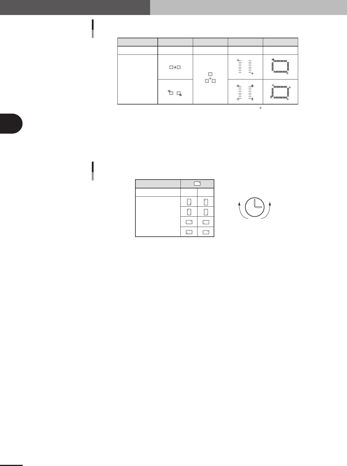
3 - 10 3 Creating the PCB data 3. Creating the PCB information Component type Teaching method Teaching point Teaching method for different components CHIP 1 or 2-point input Tr. 1 or 3-point input SOP 2 or 4-point input …
3 -9
3
Creating the PCB data
3. Creating the PCB information
3.2 Mount parameters
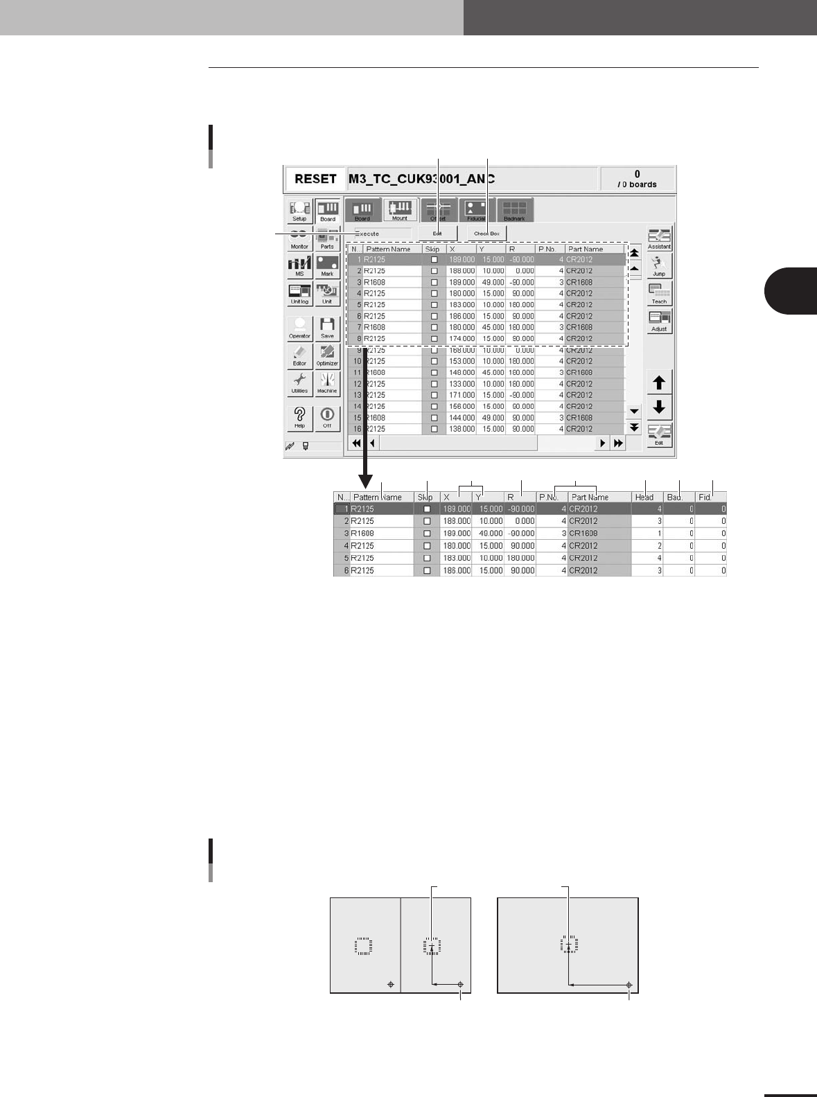
Selecting the [Mount] tab opens the screen for specifying the mount parameters such as
mounting position data and component numbers to be mounted.
1
3
245 7 8 96
Mount parameter screen
10 11
27407-5E-20
1 Execute/Skip
Select "Exec." to mount components with this mount data, or select "Skip" to perform "pass opera-
tion" without picking up and mounting components (head moves as if to pick up and mount compo-
nents).
2 Pattern Name
Enter the land pattern name or symbol (ex., R23, U12, etc.) printed on the PCB.
3 Skip
Place a checkmark when not mounting a component at this mount point.
4 X, Y
For single PCBs, enter the XY coordinate data of the center of the mounting position relative to the
PCB origin. For multi-block PCBs, enter the position data relative to the reference block. You can
also use the teaching function to enter the XY coordinate data as explained below.
Mounting position relative to PCB origin
Center of mounting position
Block 2
PCB origin
Block repeat No.1
Block 1
23404-5E-20
3 -10
3
Creating the PCB data
3. Creating the PCB information
Component type
Teaching method
Teaching point
Teaching method for different components
CHIP
1 or 2-point input
Tr.
1 or 3-point input
SOP
2 or 4-point input
QFP
2 or 4-point input
:
Teaching point
25401-5E-20
5 R
Enter the angle through which the component must be rotated after recognition before it is mounted
on the PCB. When the pickup angle is 0 deg., enter the rotating angle from the loading position, with
the counterclockwise direction specified as a plus value when viewed from above. When the pickup
angle is 90 deg. or -90 deg., see the table below.
Loading position
Pickup angle 90° -90°
Mounting angle 0°
180°
90°
-90°
Clock
PlusMinus
Mounting angle
23405-5E-20
6 P. No., Part Name
Enter the component number (data No. in the component information) to be mounted. The component
name will be input automatically according to the component number.
7 Head
Enter the head number to be used for mounting.
8 Bad (badmark)
Enter the number of the local badmark to be used for this mount data. Note that this setting is valid
only when necessary data is input on the Badmark tab screen. Enter "0" here when not using the local
badmark function.
9 Fid. (Fiducial mark)
Enter the fiducial mark number (point, local or 4-point fiducial) to be used for this mount data. Note
that this setting is valid only when necessary data is input on the Fiducial tab screen. Enter "0" here
when not using the fiducial function.
10 [Edit] button
Press this button when changing the "Execute/Skip" setting for component mounting. Selecting
"Skip" performs "pass operation" on the entire PCB without picking up and mounting components.
11 [Check Box] button
Pressing this button allows the Skip column to be edited. Pressing the [Check Box] button again
grays out the Skip column and making changes is no longer possible.
3 -11
3
Creating the PCB data
3. Creating the PCB information
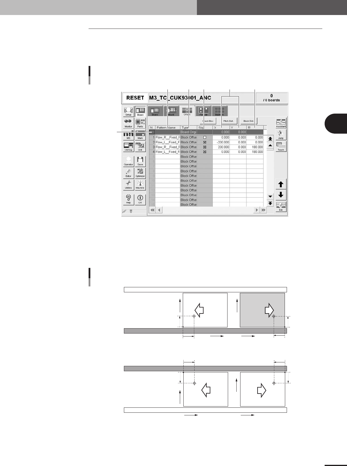
3.3 Offset parameters
Selecting the [Offset] tab opens the screen for setting the offset data for each block
relative to the reference block of a multi-block PCB consisting of two or more indepen-
dent printed circuits of the same type. The XY coordinates of the PCB origin are also
specified here.
2
1
3 4 5 6
Offset parameter screen
27408-5E-20
1 Board Origin
On the top line of the parameter list, enter the XY coordinates of the PCB origin. For standard
machines with the front conveyor rail fixed, the center of the fixed locate pin is specified as X=0.00,
Y=0.00, which is 5mm (X and Y) away from the forward corner of the PCB on the front conveyor
rail side. The PCB origin is normally set to the same position as the center of the fixed locate pin.
PCB origin
5mm
5mm
X
Y
5mm
5mm
5mm
5mm
5mm
5mm
X
Y
X
Y
X
Y
Front conveyor rail fixed
Rear conveyor rail fixed
Direction of PCB flow
23406-5E-20