M3plus_OperationManual_e.pdf - 第217页
A - 4 A Specifications 1. Specifications 1.3 Power connection terminals The power connection terminals are located inside the lower left panel on the rear of the machine. Connect the power cable leads as shown below to t…
A -3
A
Specifications
1. Specifications
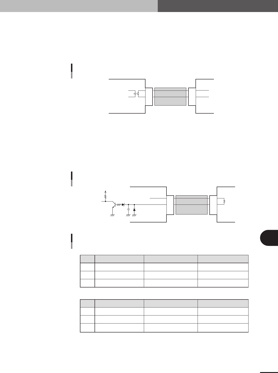
1.2.1 PREVIOUS INTERFACE connector
Signals
1. Signal output 1 during PCB carry-in (relay contact)
2. Signal output 2 during PCB carry-in (relay contact)
A PCB is carried in when the machine is ready for the next operation and the above two points (1 and
2) is connected (closed) as a PCB request signal.
1
2
3
This machine
Upstream machine
+24V
BUSY OUT
(T19043)
Cable
PREVIOUS INTERFACE circuit
23122-5E-20
1.2.2 NEXT INTERFACE connector
Signals
1. DC 24V
3. Signal input of PCB carry-out request
When the above two points (1 and 3) is connected (closed), the machine judges that a PCB carry-out
request is issued and carries out the PCB when component mount is complete.
+24V
5V
10.5kΩ
0.1µ
BUSY IN
(N1A047)
Downstream machine
This machine
Cable
NEXT INTERFACE circuit
1
3
2
23123-5E-20
1
2
3
Relay contact (zero voltage) output
Relay contact (zero voltage) output
Signal input of PCB
carry-out request
BUSY OUT
BUSY OUT
NC
Signal name
PREVIOUS INTERFACE (From this machine to upstream machine)
NEXT INTERFACE (From this machine to downstream machine)
PCB transfer signal specifications
I/O specifications Signal specificationsPin No.
1
2
3
+24V
PNP input
Signal output to request
PCB carry-out
BUSY IN (+24V)
NC
BUSY IN (N1A047)
Signal name I/O specifications Signal specificationsPin No.
25109-5E-20
A -4
A
Specifications
1. Specifications
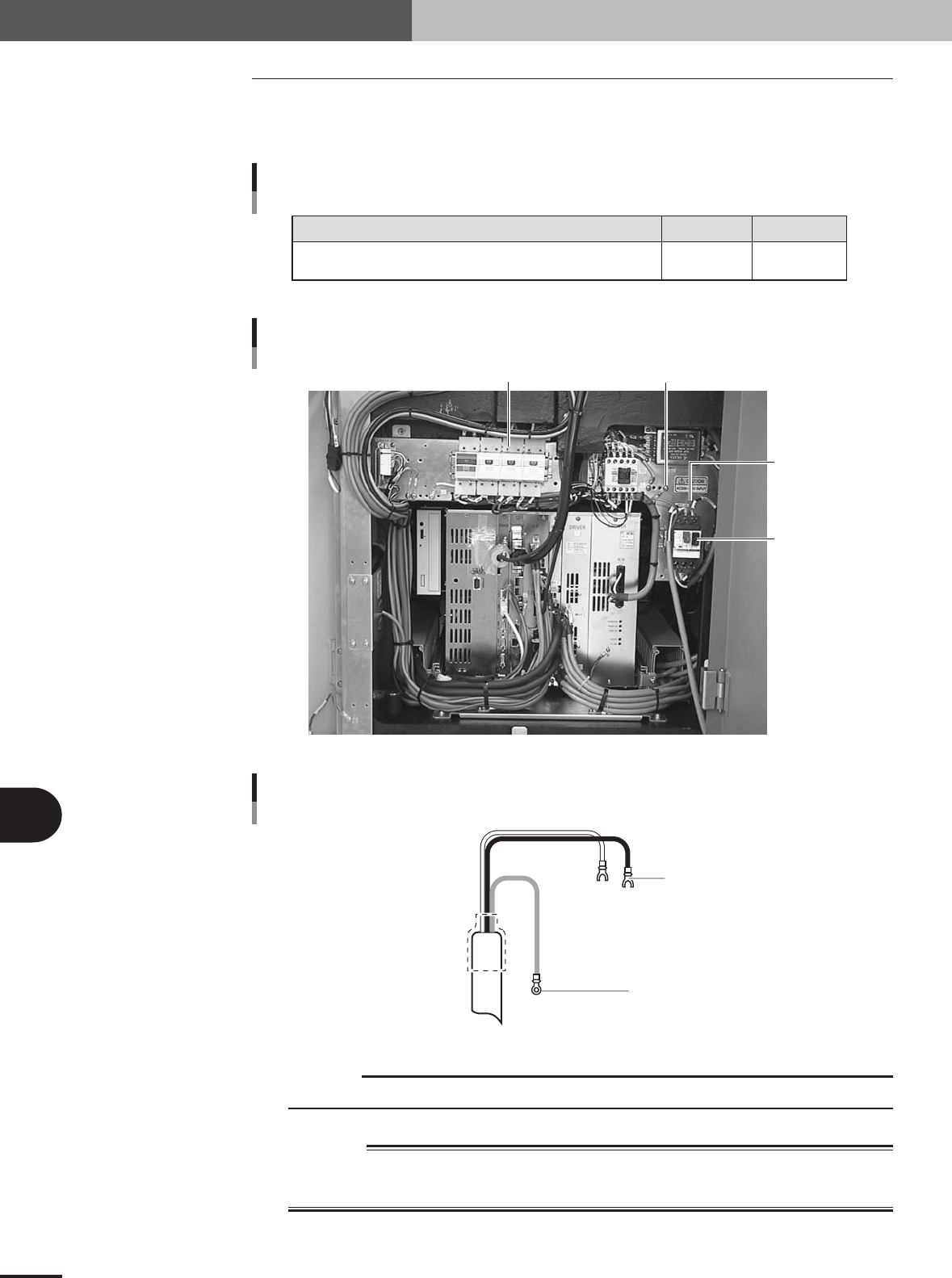
1.3 Power connection terminals
The power connection terminals are located inside the lower left panel on the rear of the
machine. Connect the power cable leads as shown below to the primary terminals L1 and
L2 on the main breaker and the ground terminal on the main unit chassis.
Power
Power supply specifications
Frequency Power capacity
Single phase AC 200 to 240V -10%, +6% 50/60Hz 2.8kVA
25111-5E-20
Power input terminal
Ground terminal
Main breaker
Power connection terminals
Breaker
23126-5E-20
Earth
Green
L=350mm
L=350mm
Round crimp terminal
Crimp terminal with insulation tube
L1
L2
Power cable example
23127-5E-20
c
CAUTION
Use a power cable that uses conductor wire having a cross section of at least 3.5mm
2
(AWG13).
w
WARNING
TO AVOID THE RISK OF ELECTRICAL SHOCK, MAKE SURE THAT THE POWER SOURCE IS
OFF BEFORE CONNECTING THE POWER CABLE. ALSO MAKE SURE THAT THE GROUND
CABLE IS SECURELY CONNECTED TO THE MACHINE.
B
Alignment Type glossary
B -5
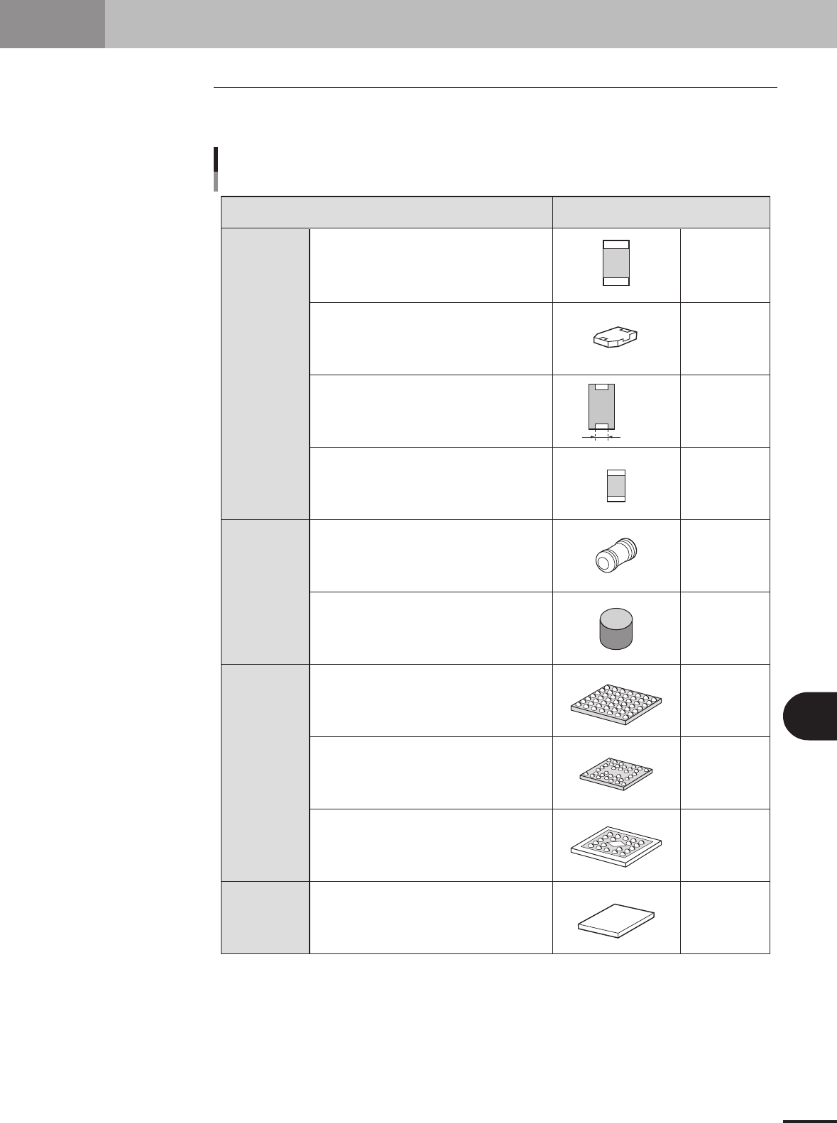
2. Alignment Type glossary
2.1 Alignment Type
Refer to the table below when setting the Alignment Type parameter on the [Parts]-
[Basic] tab.
Box type chip
Cylindrical chip
(Melf type)
BGA
Bare chip
Lead width
Alignment type setting
Chip, Ball lead component
Component type Alignment Type
Normal box type chip
Box type chip not recognized as standard chip
Box type chip whose lead width does not
match the chip width, such as tantalum capacitor
For small chip whose reflecting area is smaller
than actual area during recognition
Melf chip component
Chip component with no square part and fed
in vertical direction
Normal BGA
Flip chip
Mold body is shiny type such as ceramic
Normal bare chip
Std.Chip
Sp.Chip
Odd.2Ends
Small Chip
Melf Chip
Cylinder
BGA
Simple BGA
FlipChip
Odd.Chip
Bare.Chip
25003-5E-20