M3plus_OperationManual_e.pdf - 第40页
2 Basic oper ation 2 - 7 3. Star ting and stopping the machine This section explains routine procedures for starting and turning off the machine according to the flow charts below. Starting and turning of the machine Pro…
2 -6
2
Basic operation
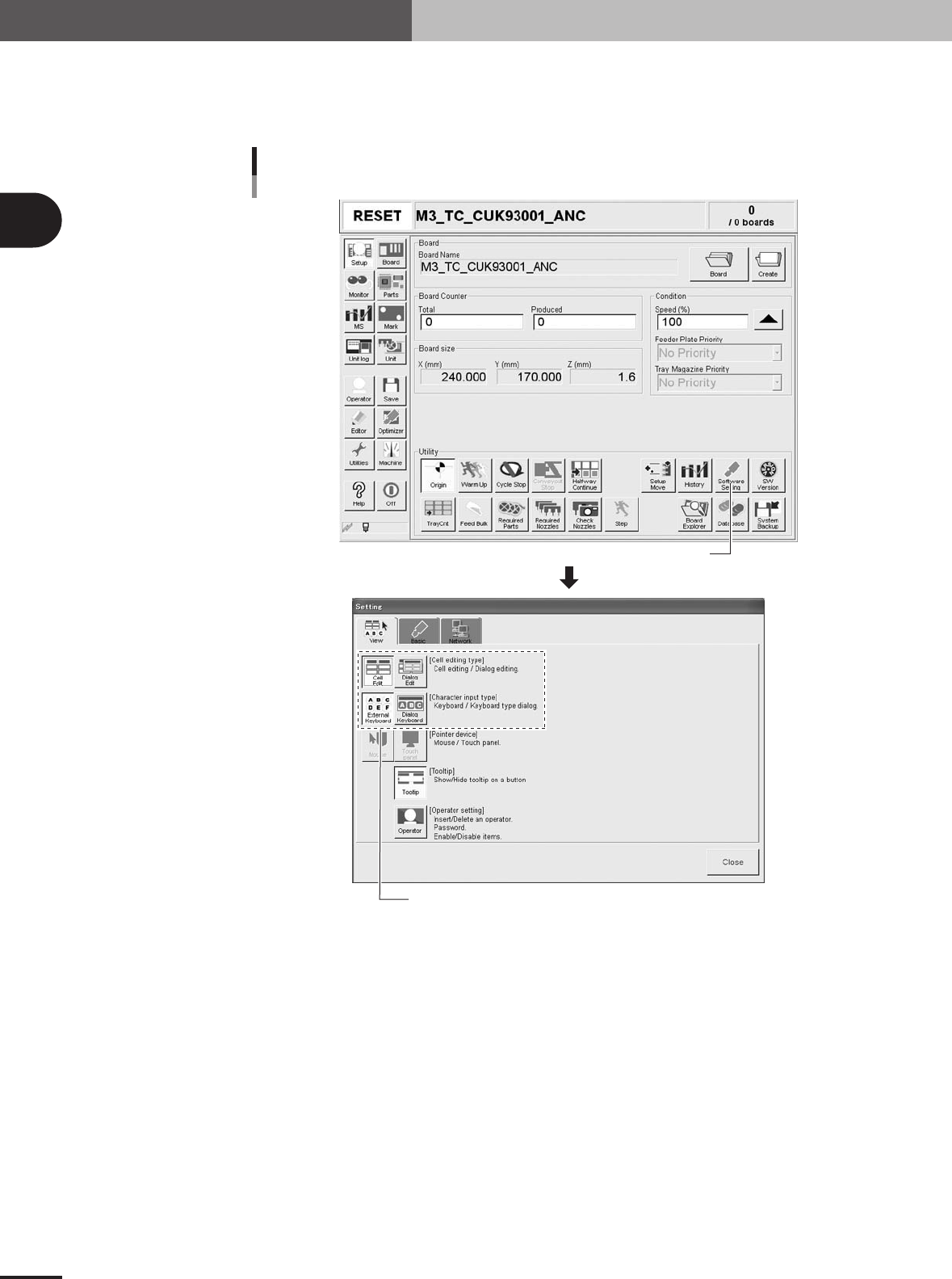
Data input method
Pressing the [Software Setting] button on the Setup screen opens the Setting window as shown
below. With the upper left four buttons in the [View] tab of the Setting window, you can select the
data input method using dialog boxes or the keyboard and mouse.
[Software Setting] button
Selecting the data input method
Select the input method.
27204-5E-20
2. Operation monitor and buttons
2
Basic operation
2 -7
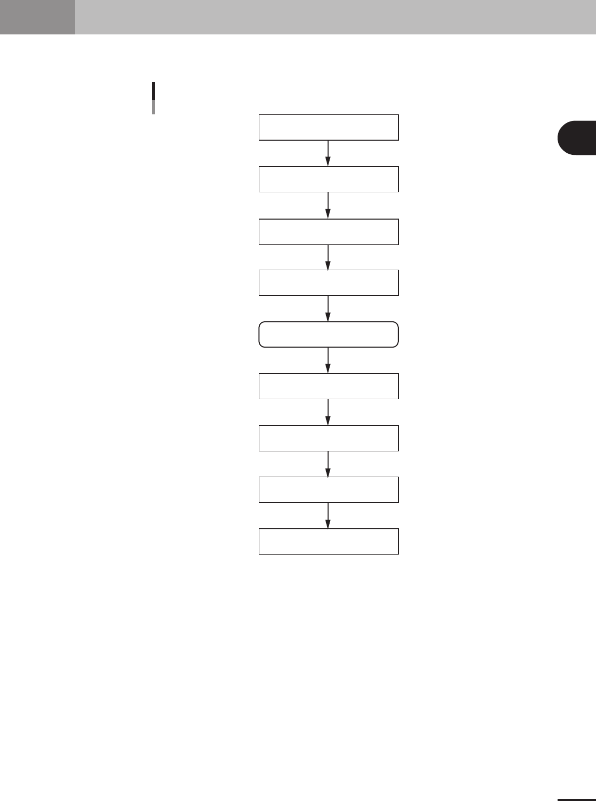
3. Starting and stopping the machine
This section explains routine procedures for starting and turning off the machine according to the flow
charts below.
Starting and turning of the machine
Production (Running)
Press emergency stop button
Return machine to origin position
Tu rn off power switch
Check before operation
Preform return-to-origin
Specify operator
Press [Off] button on screen
Program is loaded.
Return-to-origin dialog box appears.
Move-to-origin dialog box appears.
Shut down dialog box appears.
Finish PCB Production.
Setup screen appears.
Tu rn on power switch
23201-5E-20
2 -8
2
Basic operation
3. Starting and stopping the machine
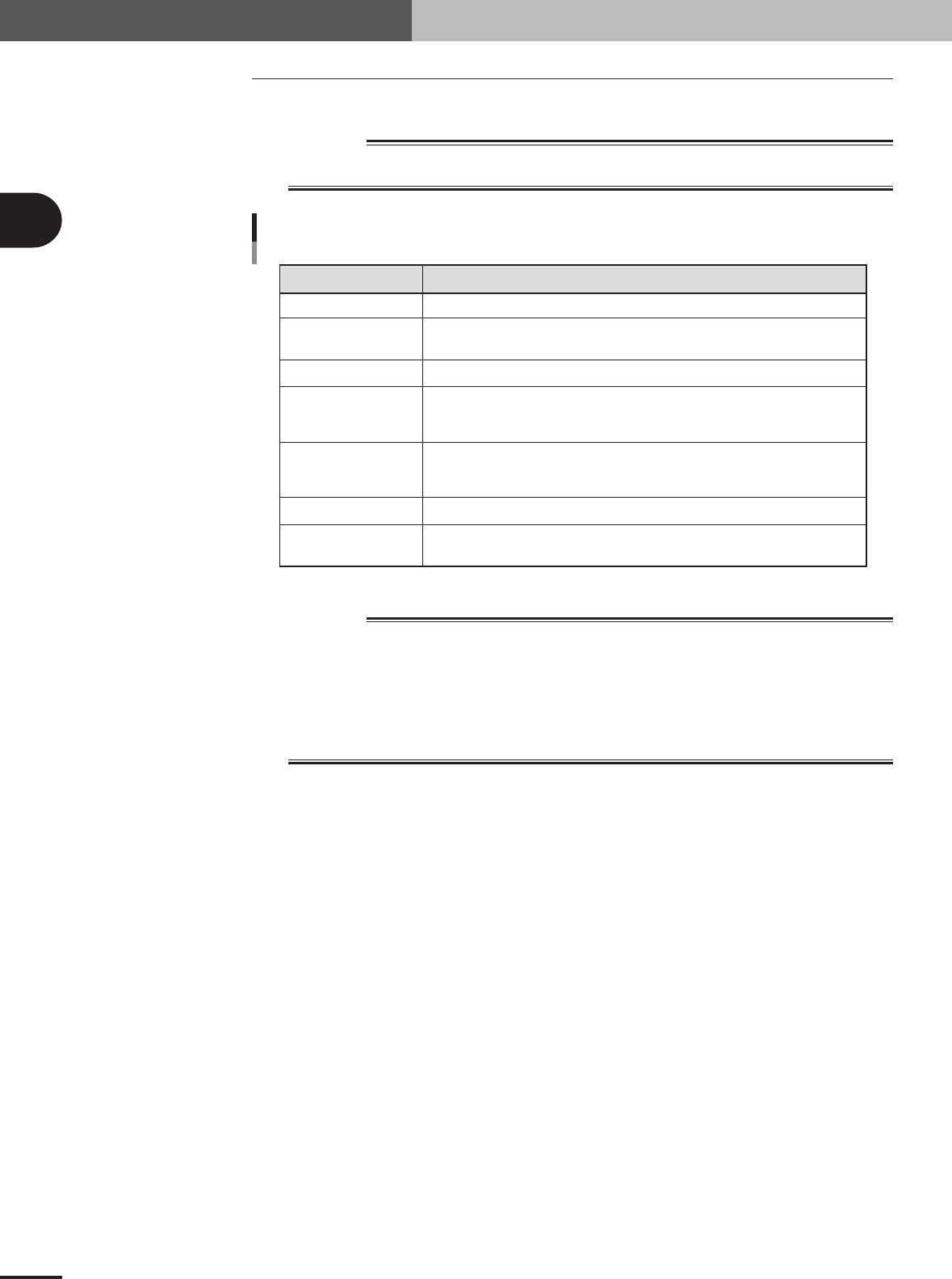
3.1 Inspection before operation
The table below shows checkpoints you should make before turning the power on.
w
WARNING
ALWAYS BE SURE TO PRESS THE EMERGENCY STOP BUTTON BEFORE MAKING
INSPECTION.
Checkpoint
Checkpoints before operation
Air
Power supply
Safety cover
Feeder
Conveyor
Head
Nozzle
Check that the black needle on the pressure gauge reads 0.55MPa.
Open the front cover of the machine and check that the specified power is connected to the
power terminal block.
Check that all covers are closed.
Check that each feeder is securely installed to the feeder plate and is not
floating.
Check that there is no foreign matter or debris on the feeders.
Check that no foreign matter or debris is on the conveyor.
Check that no parts of the conveyor unit interfere with each other such as the push-up pins
and conveyor rails.
Check that each nozzle is correctly installed to the head.
Check that the nozzle tips are not nicked, solder does not adhere to the nozzle tips,
and nozzle spring-action is smooth.
25203-5E-20
w
WARNING
THE SIGNAL LIGHT (OR WARNING LAMP) IS AN IMPORTANT DEVICE THAT INDICATES THE
MACHINE STATUS. BEFORE BEGINNING ANY OPERATION, BE SURE TO CHECK THAT THE
SIGNAL LIGHT SHOWS THE CORRECT MACHINE STATUS AS FOLLOWS:
GREEN: MACHINE IS IN AUTOMATIC OPERATION.
YELLOW: ERROR OR INTERLOCK HAS OCCURRED.
RED: MACHINE IS IN EMERGENCY STOP.
NEVER ALLOW ANY PART OF THE BODY OR ANY OBJECT TO ENTER THE MOVEMENT
RANGE OF THE HEAD ASSEMBLY WHILE THE GREEN LAMP IS LIT.