M3plus_OperationManual_e.pdf - 第150页
4 - 15 4 Using the adv anced functions 4. Setup parameters 4.1.1 Loading the saved data Even when you have reset the mounting operation during PCB production, the machine saves the mounting operation data that was in pro…
4
Using the advanced functions
4-14
4. Setup parameters
4.1 Halfway Continue function
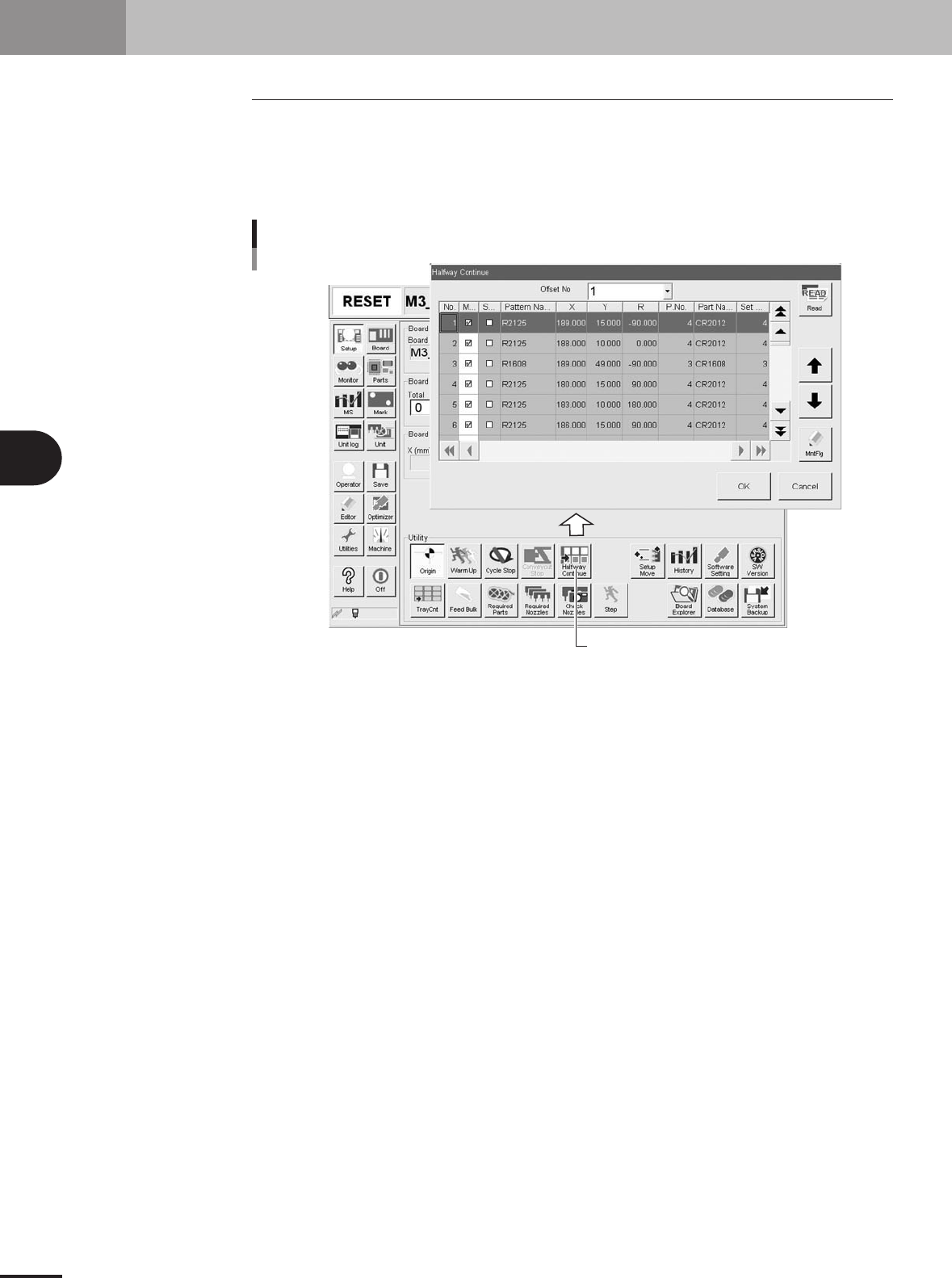
Pressing the [Halfway Continue] button on the Setup screen opens the Halfway Continue
dialog box as shown below. Even after resetting the mounting data, the Halfway Continue
function allows you to load that mounting data to mount components again at a specific
block or mount point. Note that the Halfway Continue function can be used just for the
first PCB, with routine mounting operation beginning from the next PCB.
[Halfway Continue] button
Opening the Halfway Continue dialog box
27312-5E-20

4 -15
4
Using the advanced functions
4. Setup parameters
4.1.1 Loading the saved data
Even when you have reset the mounting operation during PCB production, the machine
saves the mounting operation data that was in progress. You can load that data by press-
ing the [Read] button on the Halfway Continue dialog box, to resume the operation from
the stopped point. Since the last mounting data including error information is saved,
mounting is also performed at the mounting points at which errors occurred.
Automatic operation restarts
after loading the save data.
1
5
BLOCK NO.1
Restarting component mount by Halfway Continue function
BLOCK NO.2
2
6
3
7
4
8
1
5
2
6
3
7
4
8
1
5
BLOCK NO.1 BLOCK NO.2
2
6
3
7
4
8
1
5
2
6
3
7
4
8
:mounted
:not mounted
Reset
23307-5E-20
4.1.2 Editing mount flags
The Halfway Continue function can also be used to perform mounting for a specific
mounting point by specifying the mount data number. For example, when you have
paused mounting operation and reset the mount data, press the [Read] button to reload
the data and edit each mounting point as necessary by using the [MntFlg] button. When
the offset function for multi-block PCBs (See "3.3 Offset parameters" in Chapter 3.) is
used, the mount data in each block can also be edited. Note that this function is used only
for the first PCB, with routine mounting operation beginning from the next PCB.
[MntFlg] button
Editing mount flags
Offset No. selection box
Mounted flag (checkmark)
27313-5E-20
4-16
4
Using the advanced functions
5. Edit Assistant function
The Adjust Assistant function allows you to edit, search and replace within the selected row range.
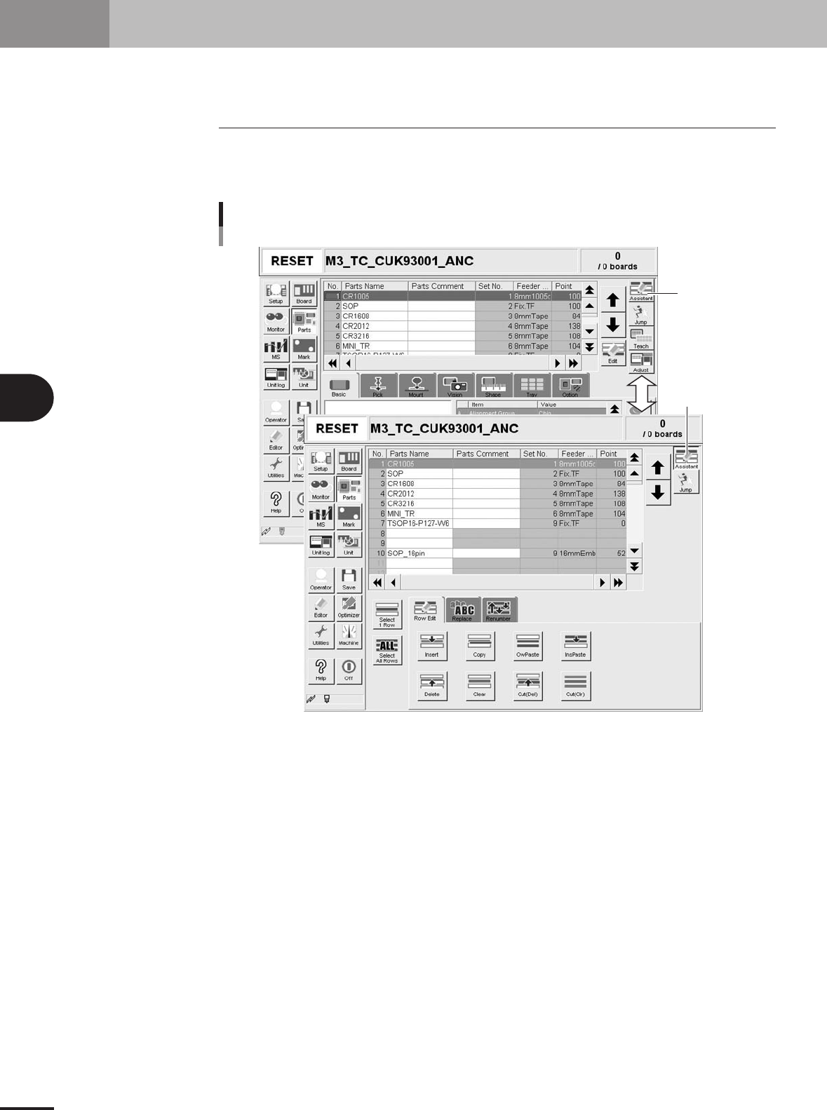
5.1 Switching to the Edit Assistant screen
When you press the [Assistant] button on the top right of the screen, the Edit Assistant
screen appears in the lower part, showing the [Row Edit] and [Replace] tabs. To return to
the previous screen, press the [Assistant] button again.
[Assistant] button
Button is depressed
when selected.
Switching to the Edit Assistant screen
27479-5E-20