M3plus_OperationManual_e.pdf - 第28页
1 - 7 1 P art names and functions 3.3 Nozzle station (option) The nozzle station accommodates various nozzles for automatic change. Nozzles can be automatically changed on all heads (Heads 1 to 4). The drawing below show…
1
Part names and functions
1-6
3. Head assembly
The head assembly is mounted on the Y arm and moves to pick up and mount components. The
following sections describe the head assembly configurations and nozzle types.
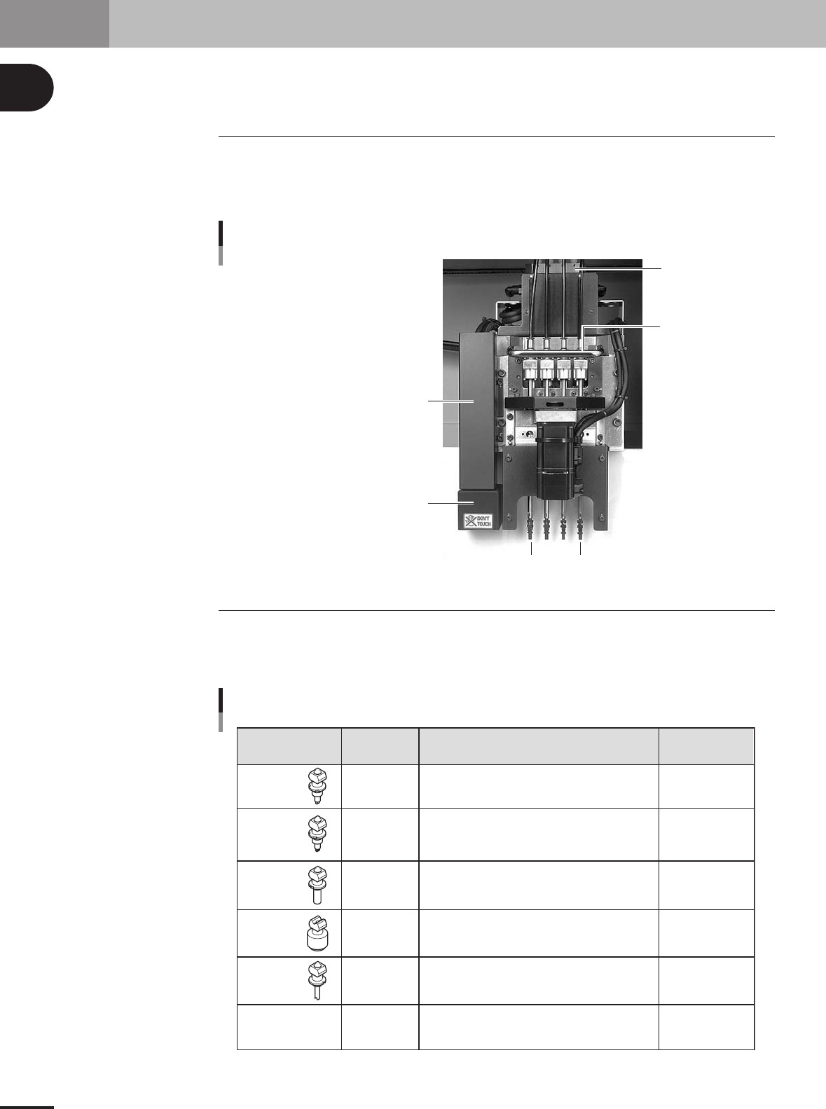
3.1 Component pickup/mount head
The head assembly has 4 in-line heads for component pickup and mounting. Head num-
bers are designated from 1 to 4, from the head closest to the fiducial mark recognition
camera. The spacing of adjacent nozzles attached to each head is 20mm, which is identi-
cal to the pitch of the feeder installation holes on the feeder plates.
4 in-line heads
Vacuum ejector
Head 4
Head 1
Moving camera
(for fiducial mark recognition and teaching)
Lighting unit
(for fiducial mark recognition and teaching)
Head movement
handle
23108-5E-20
3.2 Nozzle types
To ensure stable component pickup, the correct nozzle that matches the component must
be used. The following table shows typical nozzles which can be attached to each head.
Five standard nozzles and one custom nozzle are available for the 4 in-line heads.
Type 81A
Type 82A
Type 83A
Type 84A
Type 86A
Type 8SA
Standard nozzle
for auto nozzle
change
Standard nozzle
for auto nozzle
change
Standard nozzle
for auto nozzle
change
Standard nozzle
for auto nozzle
change
Standard nozzle
for auto nozzle
change
Up to 5mm in
outer diameter
Nozzle Type Suitable head Typical Components Remarks
0603 size chip components only
1005 to 3216 size components, mini-mold transistors, etc.
4532 to 7343 size components, 10mm SOP, etc.
10x10mm to 31x31mm size components
(some conditions should be met.)
Cylindrical capacitor (Melf type)
Custom-made nozzle
All heads
All heads
All heads
All heads
Head 1
Head 2, 3, 4
4 in-line type nozzle
25104-5E-20
1 -7
1
Part names and functions
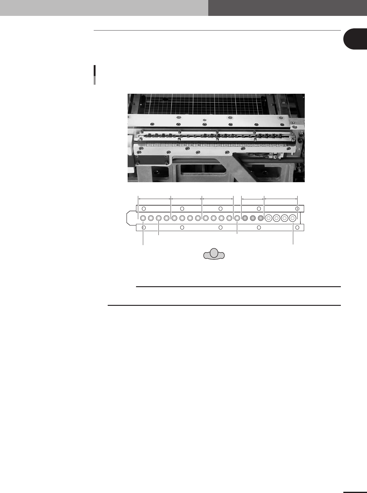
3.3 Nozzle station (option)
The nozzle station accommodates various nozzles for automatic change.
Nozzles can be automatically changed on all heads (Heads 1 to 4). The drawing below
shows the nozzle station No., allotted head No., and mating nozzles.
4
3
21432143214321432
1
Type 81A Type 82A Type 83A Type 84A
Type 86A
Type 8SA
(Special)
Nozzle station
Option
Nozzle Station No.1
Nozzle Station No.20
Head No.
Front of machine
23113-5E-20
c
CAUTION
Each nozzle has the orientation. After removing a nozzle by hand, always return it in the
specified position on the nozzle station.
3. Head assembly
1
Part names and functions
1-8
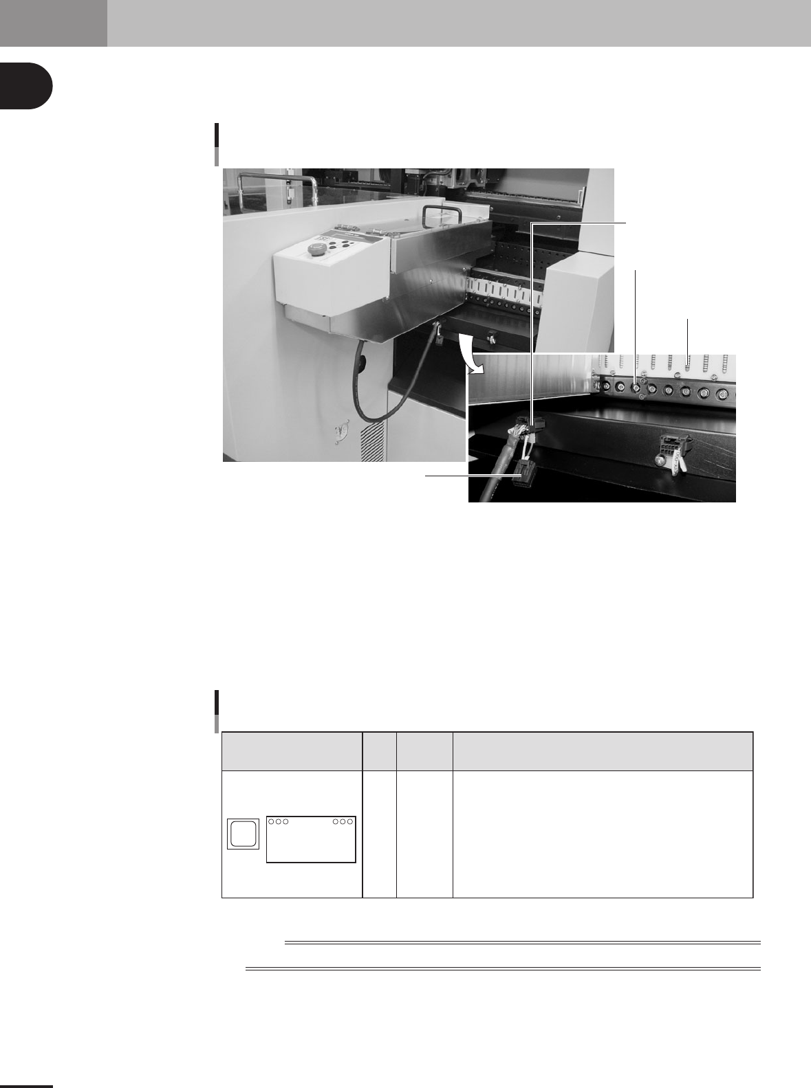
4. Feeder plate section
The standard machine has a compact feeder plate with 16 feeder set positions for installing tape
feeders and stick feeders. Under the feeder plate, there are connectors for signal exchange between
the mounter and feeders, as well as power supply connectors and air connectors for driving optional
units.
Feeder drive air outlet
Signal contact
(8-pin contact)
Connector for TSF1
Shorting connector for TSF1
Feeder plate
23117-5E-20
Signal connector
This connector is used to exchange signals between the mounter and feeders.
Feeder drive air inlet
Supplies the drive air to the feeders.
Connector for TSF1
This connector is used to supply power and signals to the TSF1 (tray shuttle feeder). When this
connector is not used, always attach the shorting connector to it.
Accessible
feeder set No.
Configuration Head
Attachable feeders
1
16
Feeder plate configuration
1
2
3
4
1 to 13
1 to 14
1 to 15
1 to 16
Tape feeders 8mm : Occupies a width of 1 feeder set position
12, 16mm : Occupies a width of 2 feeder set positions
24, 32mm : Occupies a width of 3 feeder set positions
Stick feeders
Occupies a width of 2 or 3 feeder positions
TSF1 Up to 2 units
(One unit occupies a width of 7 feeder set
positions.)
16 in-line feeder set points
(20mm pitch)
23118-5E-20
n
NOTE
Tape feeders with a 15-inch reel and TSF1 can only be used with machines designed for large type tape feeders.