M3plus_OperationManual_e.pdf - 第141页
4 - 6 4 Using the adv anced functions 2. Parts parameters 4 Specify the alternative component numbers. When data No. 12 and No. 13 in the data list are used as alternative components for data No. 1, make the settings as …
4 -5
4
Using the advanced functions
2. Parts parameters
2.1.2 Setting the alternative components
The following steps explain how to set the alternative components using tape feeders.
1
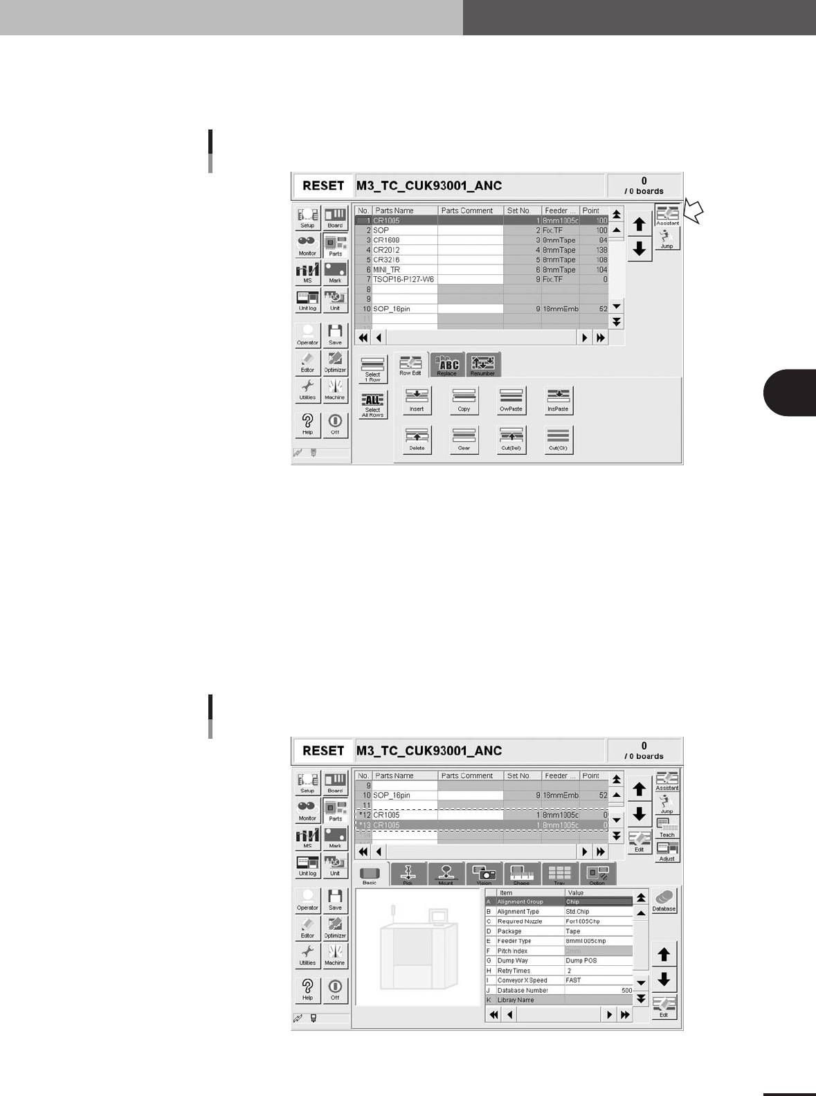
Open the [Parts] - [Option] tab screen
Parts Information screen
Edit Assistant mode
27474-5E-20
1
Select the source component.
In the upper grid display, select the source component to create the alternative
component data.
2
Enter the Edit Assistant mode and press the [Copy] button.
Press the [Assistant] button at the upper right to enter the Edit Assistant mode and
then press the [Copy] button on the [Row Edit] tab that appears.
3
Paste the data.
Select an empty row in the grid display and press the [InsPaste] button. For example,
paste the data onto data rows No. 12 and No. 13 to use two tape feeders as alterna-
tive components.
Pasting the data as alternative components
27476-5E-20
4 -6
4
Using the advanced functions
2. Parts parameters
4
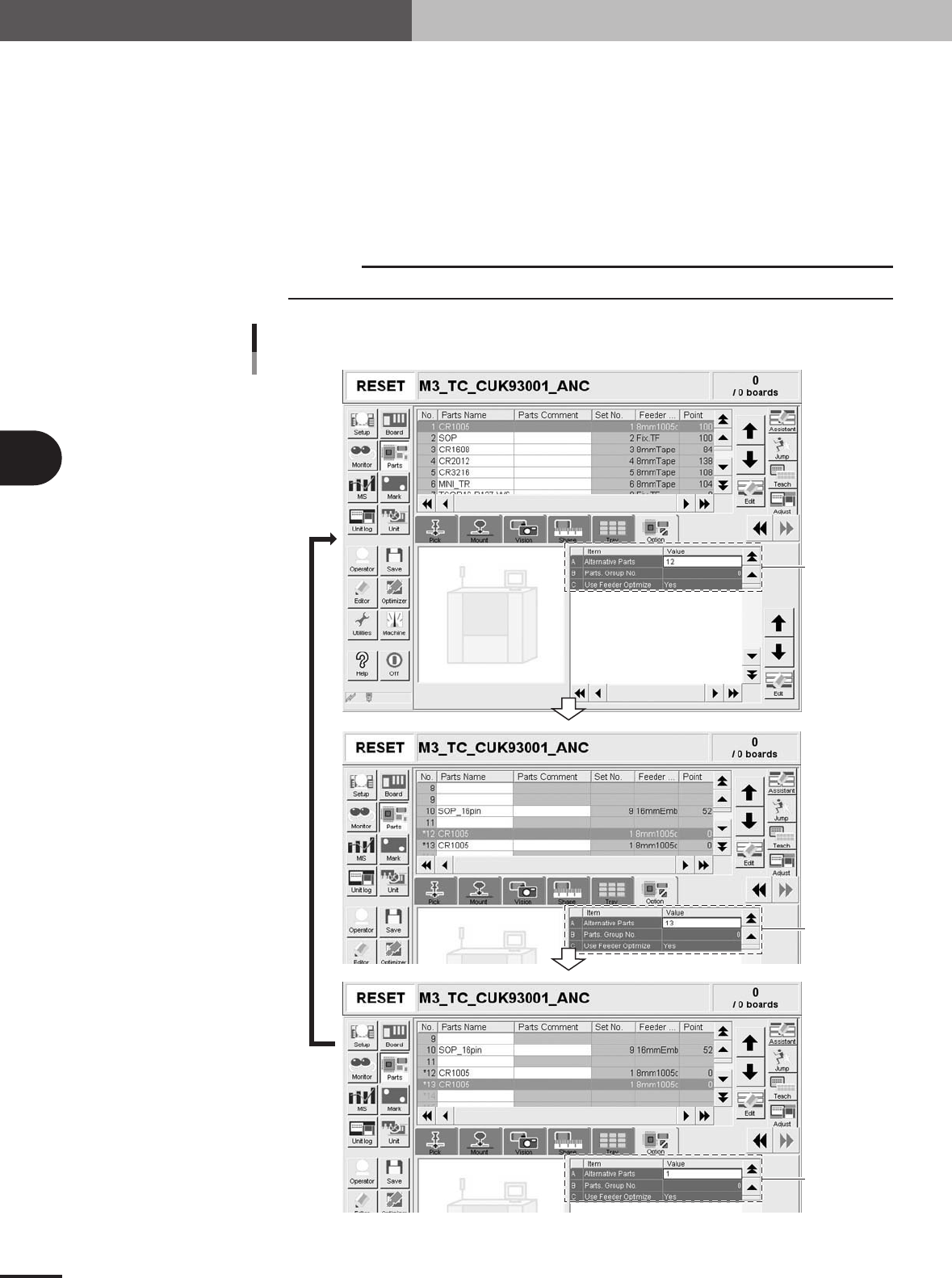
Specify the alternative component numbers.
When data No. 12 and No. 13 in the data list are used as alternative components for
data No. 1, make the settings as follows.
1.Select data No. 1 and set the "Alternative Parts" parameter to "12".
2.Select data No. 12 and set the "Alternative Parts" parameter to "13".
3.Select data No. 13 and set the "Alternative Parts" parameter to "1".
The settings above mean that the alternative component for No. 1 is No. 12, that
for No. 12 is No. 13, and that for No. 13 is No. 1, just like making a loop as an
alternative component group.
c
CAUTION
Data No. for alternative components must make a loop.
Set to "12".
Set to "13".
Set to "1".
Alternative component number settings
27477-5E-20
4 -7
4
Using the advanced functions
2. Parts parameters
2.2 Using "Parts Group No."
Use "Parts Group No." on the [Parts]-[Option] tab when components must be mounted in
a specific order, for example in the following cases.
1. Short (low profile) components should be mounted before mounting tall components to prevent the
nozzles from interfering with mounted components.
2. Components should be mounted on a component (chip on chip, etc.).
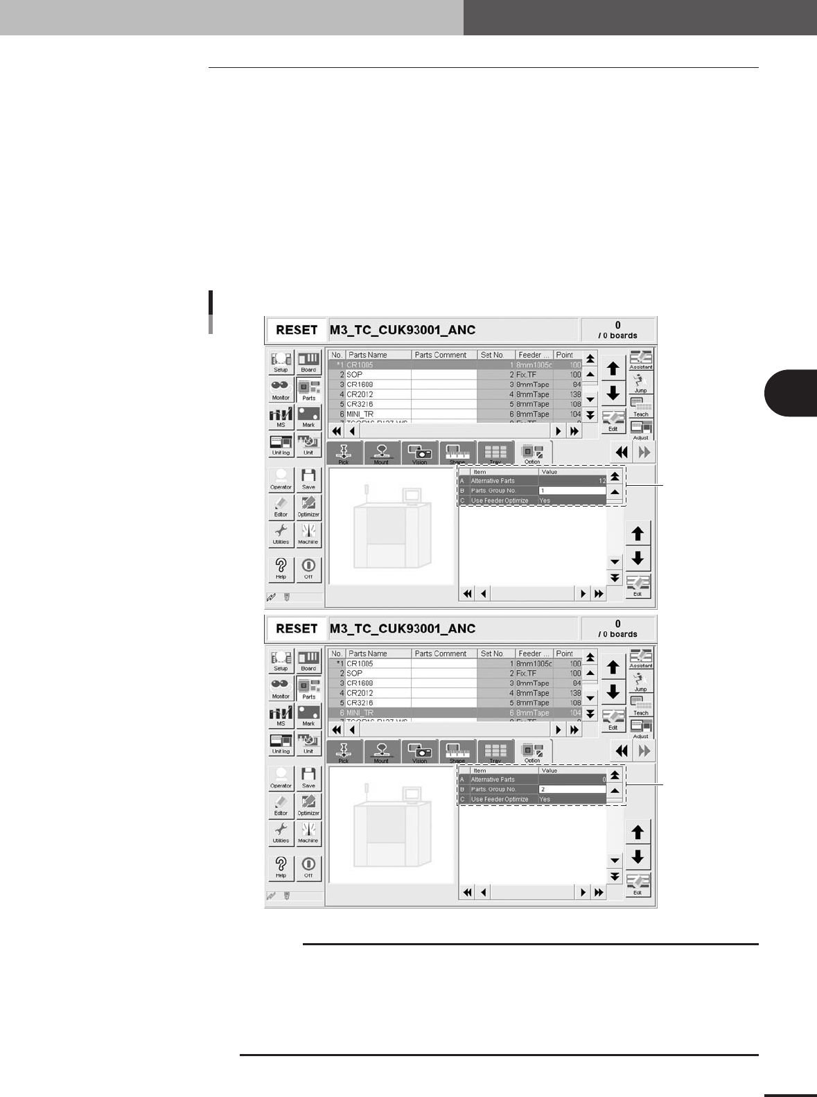
Components can be grouped by a number specified in the "Parts Group No." parameter.
When data optimization is executed after setting the "Parts Group No." parameter, the
mount sequence is determined so that a component group of the smallest number will be
mounted first. For example, when all components are classified into group 1 and group 2.
Components of group 2 are mounted after components of group 1 have been mounted. (In
the example below, component No. 6 (set to group 2) is mounted after other components
(set to group 1) have been mounted.
Set to "1" to mount
components first.
Set to "2" to mount
components after
group 1.
Setting "Parts Group No."
27478-5E-20
c
CAUTION
Numbers specified in the "Parts Group No." parameter determines the order of mounting
components, but this order is enabled only after executing data optimization. Always execute
data optimization to enable the "Parts Group No." parameter settings.
All components must be classified into any group, so a number of 1 or larger must be given to
the "Parts Group No." parameter of all components. For example, if you want to mount a kind of
components after other components have been mounted, set that kind of components to group
2 and all other components to group 1.