M3plus_OperationManual_e.pdf - 第252页
2 - 7 2 Ho w to handle and operate the TSF1 LCD display The LCD display shows the following status of the TSF1. LCD display Character string Display Status display description [ASCIAOLE] [ORG] [ID:1] [-143.000] Status di…
2 -6
2
How to handle and operate the TSF1
2.4 Manual operations
n
NOTE
You can manually operate the TSF1 to return the shuttle to the origin position or to move it to the tray
replacement position. Use these operations in the following cases.
[Example 1]
When replacing the tray before the specified number of components has been mounted:
In normal operation, when all components on the tray run out, the TSF1 detects this and the shuttle
automatically moves to the tray replacement position where you can replace the empty tray with a
new tray. For example, if only half of the full number of components remain on the tray and those
components are all used up before the specified number of components is mounted, a pickup error
will occur. If this happens, you must manually move the shuttle to the tray replacement position to
replace the empty tray with a new tray.
[Example 2]
When moving the shuttle during maintenance or inspection:
When you want to move the shuttle to spread grease after applying it to the shuttle axis or to check
for abnormal noise or vibration during inspection, use the JOG operation.
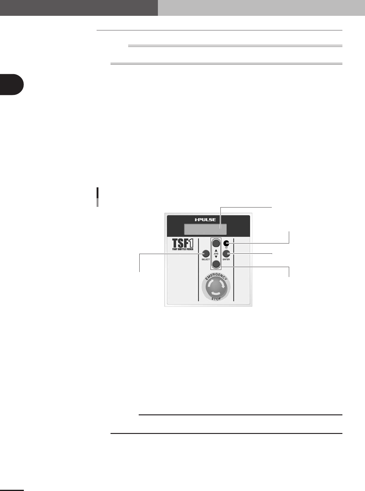
Operation panel switch description
ENTER button
ID setting dial
JOG button
SELECT button
LCD (Liquid crystal display)
Operation switch panel
73104-5V-00
SELECT button
Use this button to select the manual operation. Select "SET" to move the shuttle to the tray
replacement position or "ORG" to return the shuttle to the origin.
ENTER button
Press this button to perform the manual operation selected with the SELECT button. (The selected
operation is entered the first time you press this button, and is run the second time you press it.)
JOG button
1. Moves the shuttle in JOG mode.
Pressing the [▲] button moves the shuttle toward the work position (mounter side).
Pressing the [▼] button moves the shuttle toward the tray replacement position (TSF1 operation
switch panel side).
c
CAUTION
The JOG buttons and ENTER button are disabled during emergency stop or automatic
operation or when the head (Z-axis) of the mounter is at a point lower than the specified height.
2. Adjusts the LCD backlight brightness.
When the mounter power switch is turned on, the LCD (liquid crystal display) shows the TSF1
software version information for about 2 seconds. During this period, pressing the JOG button
once enters the adjustment mode for LCD backlight brightness. The brightness can be adjusted in
32 steps. Press the [▲] button to make the display darker, or press the [▼] button to make it
brighter.
2 -7
2
How to handle and operate the TSF1
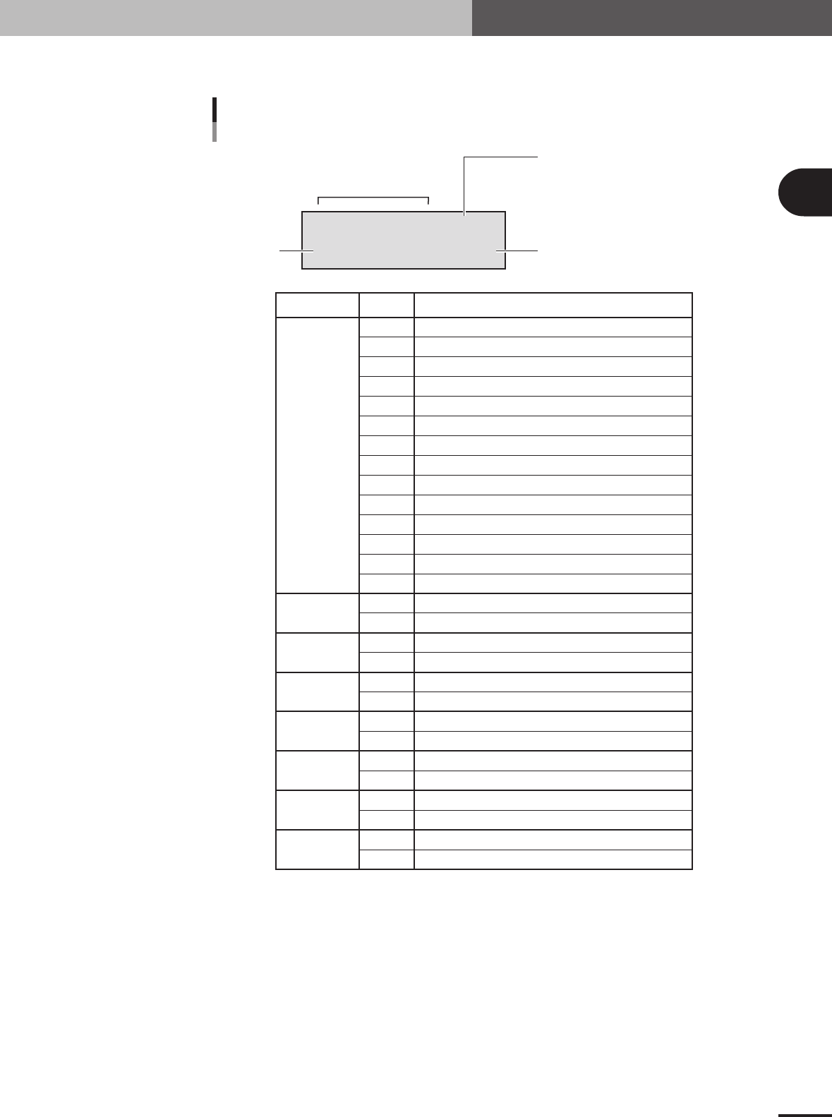
LCD display
The LCD display shows the following status of the TSF1.
LCD display
Character string Display Status display description
[ASCIAOLE] [ORG]
[ID:1] [-143.000]
Status display
(#1 to #8 from left to right)
Manual operation setting display
ORG: Return to origin
SET: Move to tray replacement position
OK?: Confirmation display
Shuttle axis coordinateID number
#1
#2
#3
#4
#5
#6
#7
#8
A
B
C
D
E
F
G
H
I
J
K
L
M
N
S
D
C
None
I
None
A
None
O
None
L
None
E
None
No alarm (normal operation)
ROM error
Sensor wiring is broken.
Power supply voltage is too high.
Power supply voltage is too low.
Initialization error
Servo error
Servo error (nanosecond stop)
Over speed
Regenerative voltage is higher than specified
Return-to-origin error
Deviation counter OVF
Absolute value counter sign inverted
Thrusting movement completed before reaching current limit
Z-axis is at a safe height. (JOG movement permitted)
Z-axis is at an unsafe height. (JOG movement not permitted)
Amplifier operation completed.
Amplifier operation incomplete.
Amplifier in-position status (within range)
Amplifier in-position status (outside range)
Amplifier alarm
Amplifier no alarm (normal operation)
Servo ON status
Servo OFF status
Over amplifier software limits or hardware limits
Within amplifier software limits or hardware limits
Error in amplifier command error
No error in amplifier command (normal operation)
73205-5V-00
2 -8
2
How to handle and operate the TSF1
2.5 Production
The basic procedure for production using the TSF1 is explained below.
n
NOTE
For information about how to create tray component data, refer to Chapter 3, "Creating the PCB data", in the M
CUBE PLUS operation manual.
1
Set the component tray on the shuttle of the TSF1.
1.To continue the previous production, start it without resetting the component
count. (The component count is stored in memory.) When you use a new tray and
want to reset the component count, press the [TrayCnt] button on the Setup screen
and clear the component count.
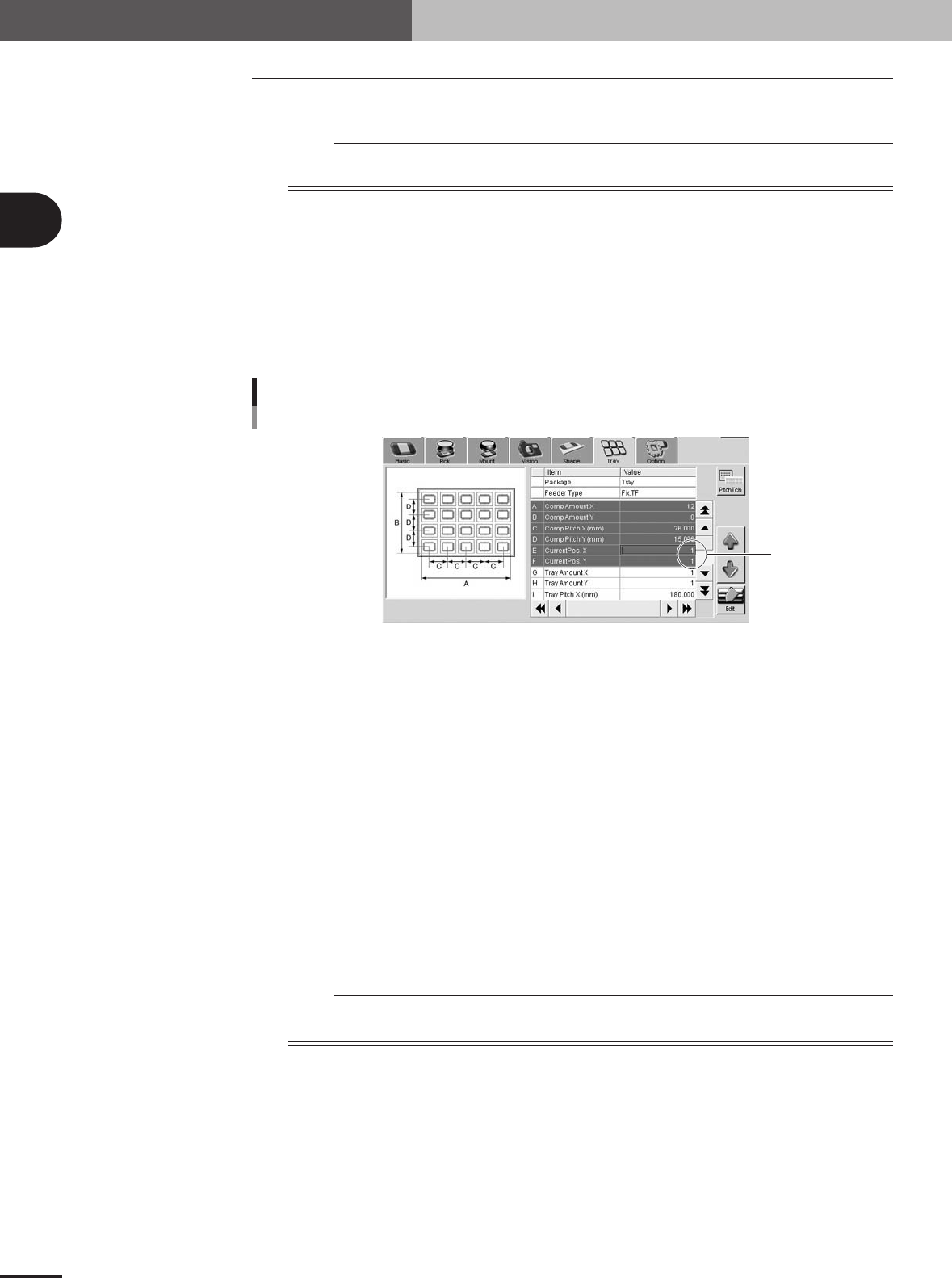
2.If you want to start picking up a component from the specified position on the tray,
open the [Parts]-[Tray] tab and, in the "Current Pos. X" and "Current Pos. Y" fields,
set the position from which to start picking up a component.
Current Pos. XY
Current Pos. XY
77206-5V-00
2
Start the production.
1.The production starts by picking up the components from the component count
position that was stored in memory when the previous production ended or from
the newly specified position on the tray.
2.When the last component has been picked up, a "tray empty error" is issued and
the mounter stops while the last component is still picked up by the head. The
shuttle then automatically moves to the tray replacement position and production is
temporarily stopped.
3
Replace the component tray.
After pressing the emergency stop button on the TSF1, open the upper safety cover
and replace the component tray with a new one.
4
Resume the production.
Close the upper safety cover and release the emergency stop button. Then press the
[READY] button on the mounter to reset the emergency stop and press the [START]
button to resume production. The component count is cleared automatically.
n
NOTE
If you want to finish the production after mounting the tray component that was last picked up (without replacing
the tray), follow the steps below.
1.A "tray empty error" is issued when the last tray component has been picked up.
2.Press the [ERROR CLEAR] button on the mounter.
3.Press the [START] button to resume production.
4.The last tray component is mounted on the PCB. In this case, a component pickup
error will occur in the next pickup cycle because the component count is
automatically cleared.
e