M3plus_OperationManual_e.pdf - 第77页
3 - 12 3 Creating the PCB data 3. Creating the PCB information When setting the PCB origin at a position other than the locate pin as shown below, enter the XY coordinates relative to the locate pin position. Setting PCB…
3 -11
3
Creating the PCB data
3. Creating the PCB information
3.3 Offset parameters
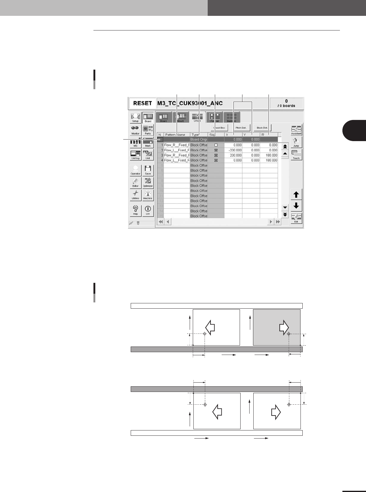
Selecting the [Offset] tab opens the screen for setting the offset data for each block
relative to the reference block of a multi-block PCB consisting of two or more indepen-
dent printed circuits of the same type. The XY coordinates of the PCB origin are also
specified here.
2
1
3 4 5 6
Offset parameter screen
27408-5E-20
1 Board Origin
On the top line of the parameter list, enter the XY coordinates of the PCB origin. For standard
machines with the front conveyor rail fixed, the center of the fixed locate pin is specified as X=0.00,
Y=0.00, which is 5mm (X and Y) away from the forward corner of the PCB on the front conveyor
rail side. The PCB origin is normally set to the same position as the center of the fixed locate pin.
PCB origin
5mm
5mm
X
Y
5mm
5mm
5mm
5mm
5mm
5mm
X
Y
X
Y
X
Y
Front conveyor rail fixed
Rear conveyor rail fixed
Direction of PCB flow
23406-5E-20
3 -12
3
Creating the PCB data
3. Creating the PCB information
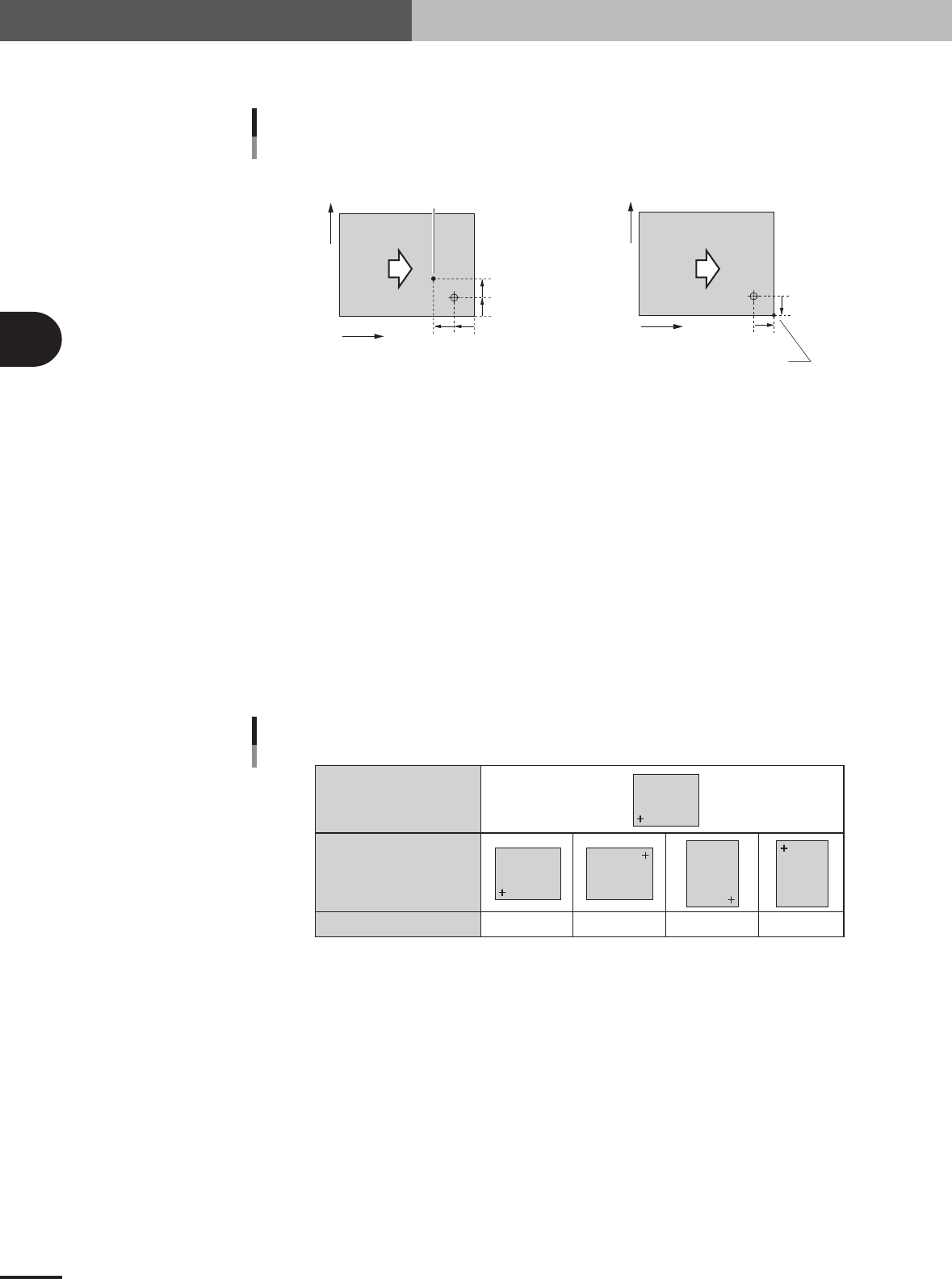
When setting the PCB origin at a position other than the locate pin as shown below, enter
the XY coordinates relative to the locate pin position.
Setting PCB origin at a position other than locate pin
When setting the PCB origin at
the corner of a PCB, enter
"X=5.00" and Y=-5.00.
5mm
5mm
X
Y
5mm
5mm
5mm
5mm
X
Y
Direction of PCB flow
When setting the PCB origin
at this point, enter "X=5.00" and Y=5.00.
• PCB origin ≠ Locate pin position • PCB origin = PCB corner
Direction of PCB
flow
23407-5E-20
2 Pattern Name
Enter the block name.
3 Type
The PCB origin is specified on the top line, and block offset data on the second and subsequent lines.
4 Skip
Place a checkmark when not mounting components in this block.
5 XY
Enter the XY coordinates of the origin in each block relative to the PCB origin. You can use the
[Teach] button to enter the XY data or trace the specified data.
6 R
Enter the rotation angle of each block with respect to the reference block. You can use the [Teach]
button to enter the R data or trace the specified data.
Reference block direction
Block direction
R data
R data
0° 180° 90° -90°
Block
Block
Block
Block
Block
25402-5E-20
3 -13
3
Creating the PCB data
3. Creating the PCB information
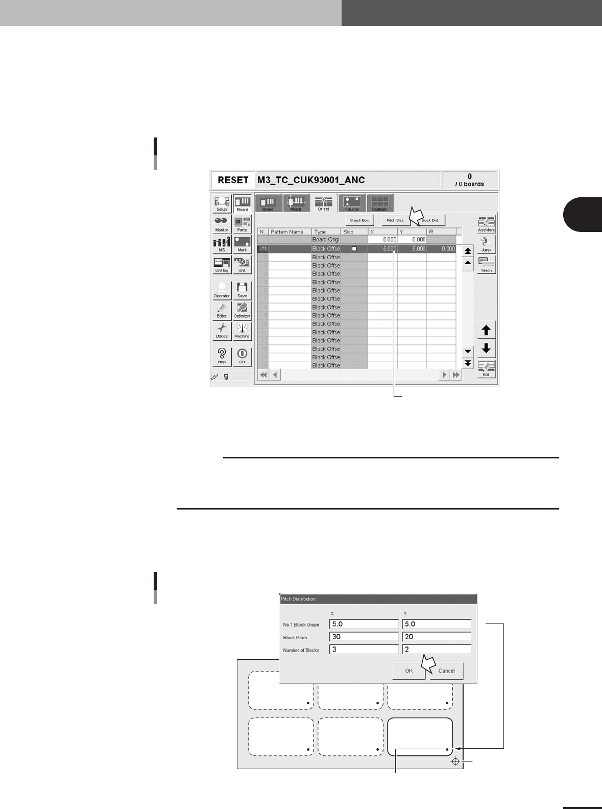
3.3.1 Pitch distribution function
This "pitch distribution" function allows you to set block offset data by specifying the
block pitch and the number of blocks.
1
Enter the block offset for block No.1.
In the X and Y fields in the No.1 row, enter the block offset from the PCB origin. This
is used as the reference coordinates for other blocks. You do not have to enter offset
here if the reference coordinates are the same as the PCB origin position.
Entering the block offset for block No.1
Offset data for block No.1
27315-5E-20
2
Press the [Pitch Dist.] button
The "Pitch Distribution" dialog box appears.
c
CAUTION
The following conditions must be met to run the pitch distribution function.
• No offset data is entered for blocks other than block No.1.
• Offset coordinates after pitch distribution will be set within the range from –999.999 to 999.999.
• The number of blocks after pitch distribution does not exceed 512.
3
Enter the block pitch and the number of blocks.
When the "Pitch Distribution" dialog box appears, enter the block pitch and the
number of blocks in the X and Y directions, then press the [OK] button. The pitch
distribution will start.
Pitch distribution settings
Offset data for block No.1
PCB origin
X
Y
27420-5E-20