M3plus_OperationManual_e.pdf - 第219页
B - 6 B Alignment T ype glossar y 2. Alignment T ype glossary Component with leads protruding from one direction. Component with leads protruding from two directions and the number of leads diagonally positioned is diffe…
B
Alignment Type glossary
B -5
2. Alignment Type glossary
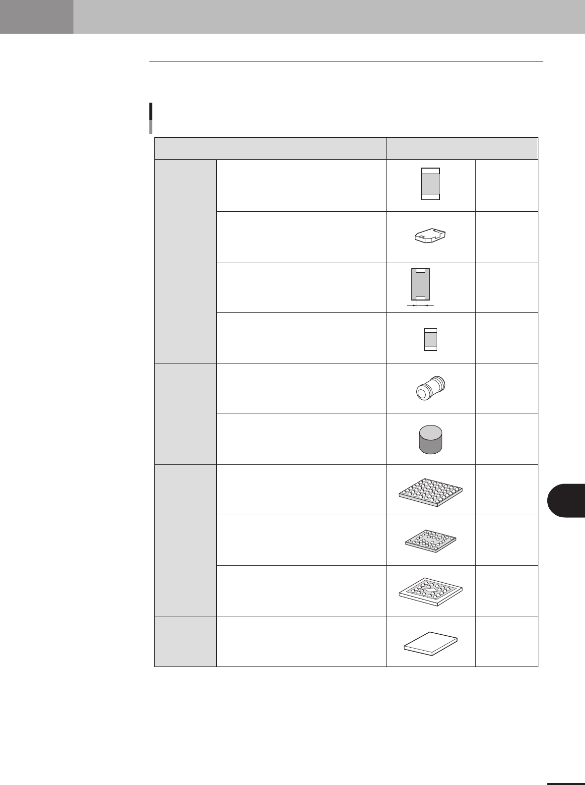
2.1 Alignment Type
Refer to the table below when setting the Alignment Type parameter on the [Parts]-
[Basic] tab.
Box type chip
Cylindrical chip
(Melf type)
BGA
Bare chip
Lead width
Alignment type setting
Chip, Ball lead component
Component type Alignment Type
Normal box type chip
Box type chip not recognized as standard chip
Box type chip whose lead width does not
match the chip width, such as tantalum capacitor
For small chip whose reflecting area is smaller
than actual area during recognition
Melf chip component
Chip component with no square part and fed
in vertical direction
Normal BGA
Flip chip
Mold body is shiny type such as ceramic
Normal bare chip
Std.Chip
Sp.Chip
Odd.2Ends
Small Chip
Melf Chip
Cylinder
BGA
Simple BGA
FlipChip
Odd.Chip
Bare.Chip
25003-5E-20
B -6
B
Alignment Type glossary
2. Alignment Type glossary
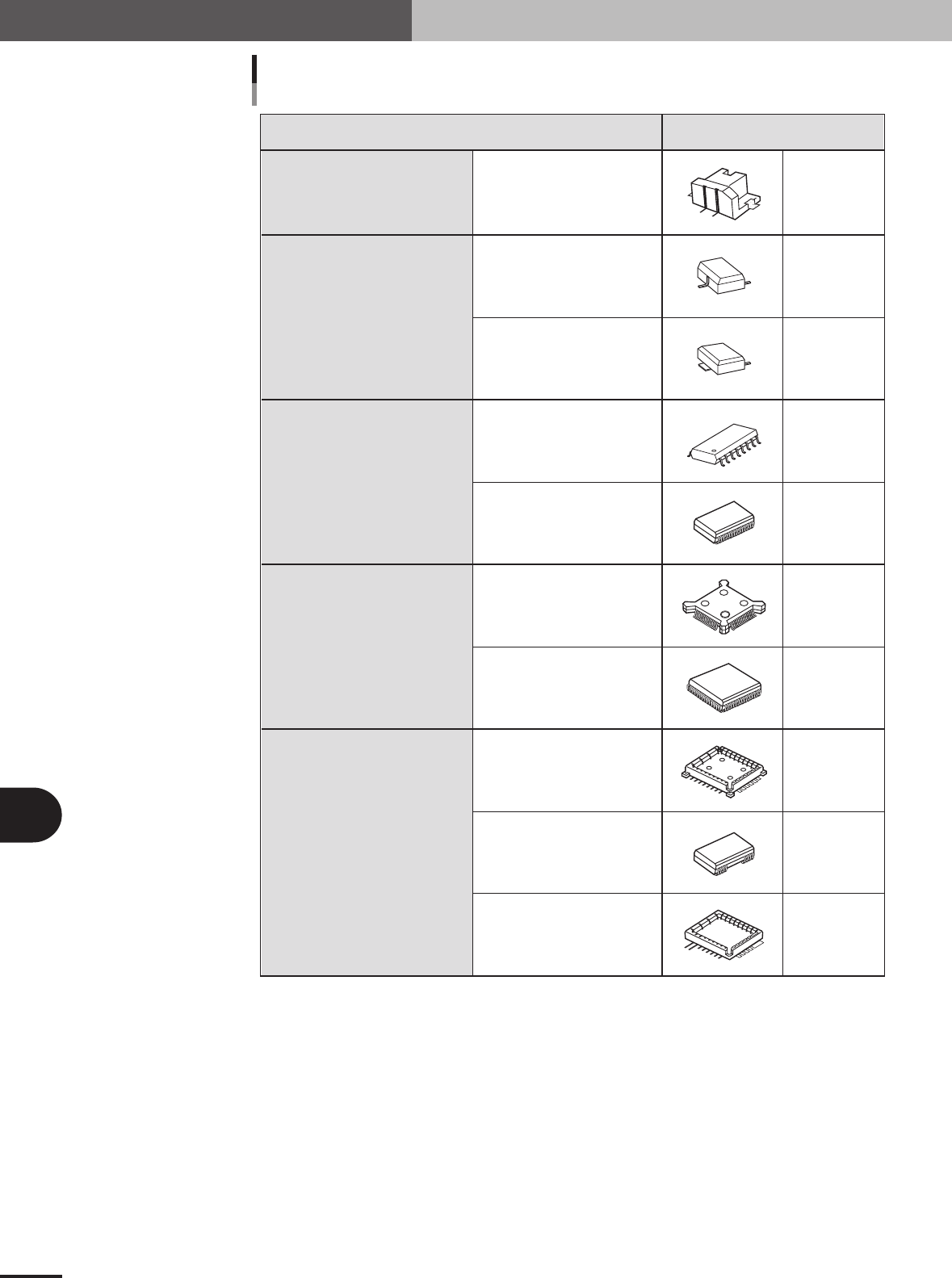
Component with leads protruding
from one direction.
Component with leads protruding
from two directions
and the number of leads diagonally
positioned is different.
Component with leads protruding
from two directions
and the numbers of lead diagonally
positioned is the same.
Component with leads protruding
from four directions
and the number of leads diagonally
positioned is the same.
Component with leads protruding
from four directions
and the number of leads diagonally
positioned is different.
Component with leads protruding
from one direction.
Oppositely positioned lead shapes
are the same
Oppositely positioned lead shapes
are different
Lead protrudes out from
molded body
Lead does not protrude out from
molded body
Lead protrudes out from
molded body
Lead does not protrude out from
molded body
Lead shape differs in
each direction
Number of leads is insufficient
Lead shapes are different in
one direction
Alignment type setting
Lead component, Nonstandard
Component type Alignment Type
Con-E
Mini-Tr/SOT
P-Tr/Con-NS
SOP
SOJ
QFP
PLCC
Con-NSEW
OffLead
Special
25004-5E-20

B -7
B
Alignment Type glossary
2. Alignment Type glossary
2.1.1 Alignment Type definition
The following explains the type and definition of "Alignment Type" settings classified
for each "Alignment Group".
Alignment Group: Chip
• Std.Chip (Standard chip)
This setting does not identify the component, but detects the four corners of the component and then
calculates the center and angle of the component. Select this setting first when recognizing box type
chips. If the component cannot be recognized by this setting, try using "Sp.Chip" or "Small Chip".
• Melf Chip
This is specially for Melf chips.
• Bare Chip
This is specially for bare chips.
• Cylinder
This is suited for components with a cylindrical shape and no direction.
• Sp.Chip (Special chip)
This setting has a parameter used to recognize "Lead Width" in addition to the "Std.Chip" setting.
Select this to recognize box type chips which cannot be recognized correctly by the "Std.Chip"
setting. If it is still difficult to recognize the component by this setting, try with "Odd.2Ends".
• Small Chip
This is suited for small chip components such as 0603 whose light-reflecting area is smaller than the
actual size.
Alignment Group: IC
• Odd.2Ends
This mode has a parameter used for recognizing the lead width and length by using "LeadWidth" and
"ReflectLL." in addition to the "Std.Chip" mode. This mode is suited for recognizing box type chips
which cannot be recognized by "Std.Chip" or "Sp.Chip".
• Mini Tr/SOT
This mode is for mini mold components with the same shape leads in the N and S direction, but
whose number of leads in each direction is different.
• P-Tr
This mode is for components having leads in the N and S direction, and whose number of leads in
each direction is different like "Mini-Tr/SOT", and also the shape of opposing leads is different.
• SOP
This is for components having the same shape leads and same number of leads in the E and W
direction, and whose leads protrude out from the molded body.
• SOJ
This is for components having the same shape leads and same number of leads in the E and W
direction like "SOP", but whose leads do not protrude out from molded body.
• QFP
This is for components having the same shape leads in four directions of N, S, E and W, and the
same number of oppositely positioned leads (N to S and E to W), and whose lead protrudes out from
molded body.
• PLCC
This is for components having the same shape leads in four directions of N, S, E and W, and the
same number of oppositely positioned leads (N to S and E to W) like "QFP", but whose leads do not
protrude out from molded body.
• OffLead
This is used for components which can be defined by "Con-NSEW" but some of the leads are
removed. Input this setting for each direction.