D系列电路图00194841-02_DC_SIPLACED12_DE+EN.pdf - 第114页
4 - 1 1 0305017 8-010201 TD3 Hauptverte iler D1/D2 D1/D2 main distributo r Hauptverteiler Main distribu tor 030501 78-010 201TD3 1 21.04.2006 Tut h Gunadi 31.10.06 402857 RS02 DT EA SIPLACE D1/D2 Orig. Repl. by. Repl. f.…
4 - 10
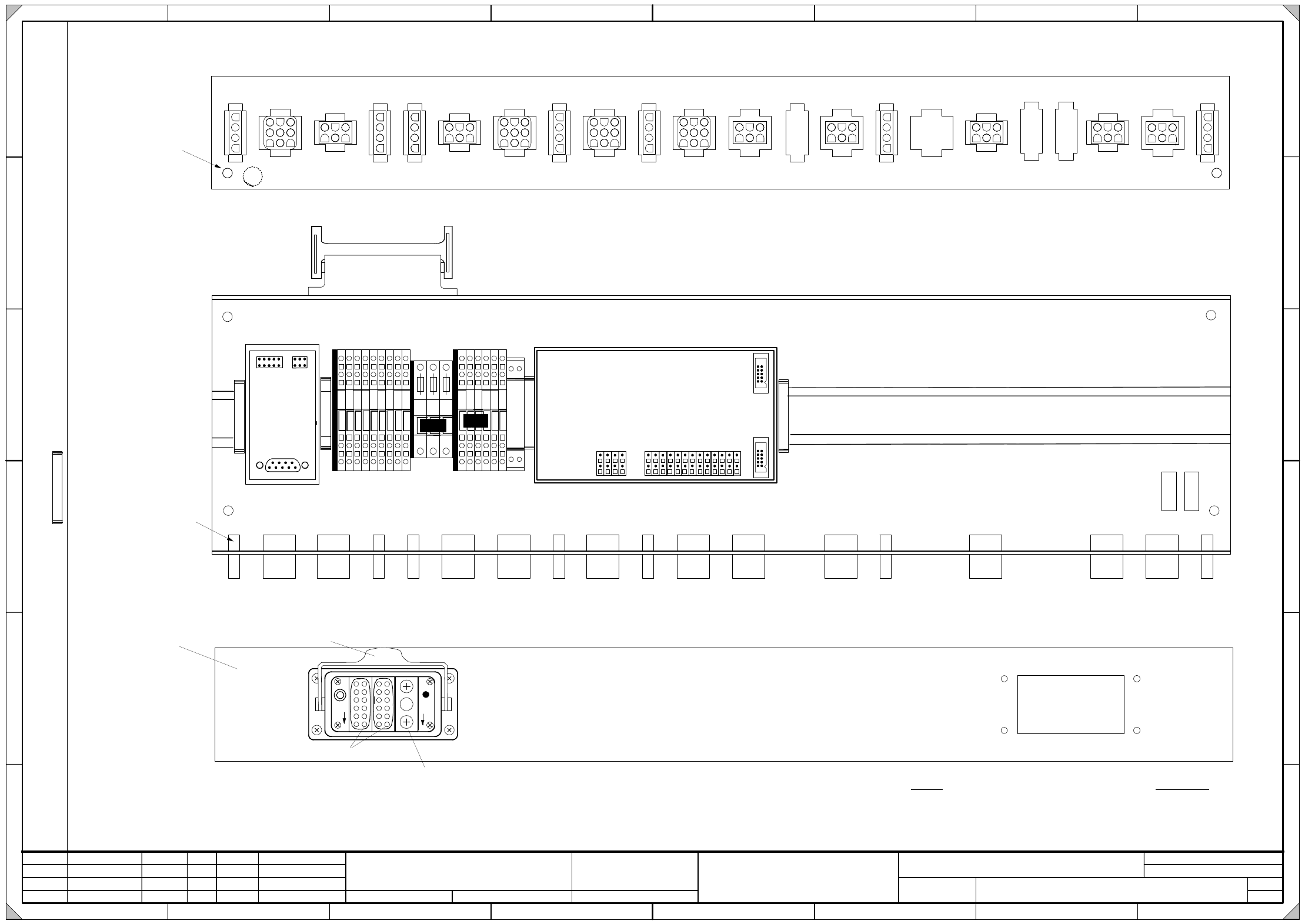
03050177-010301TD3 Unterverteiler D2
D2 sub-distributor
Unterverteiler D2
Sub-distributor D2
03050177-010301TD3
1
Tuth
Orig. Repl. by.Repl. f.
W
e
i
t
e
r
g
a
b
e
s
o
w
i
e
V
e
r
v
i
e
l
f
ä
l
t
i
g
u
n
g
d
i
e
s
e
r
U
n
t
e
r
l
a
g
e
,
V
e
r
w
e
r
t
u
n
g
u
n
d
M
i
t
t
e
i
l
u
n
g
i
h
r
e
s
I
n
h
a
l
t
s
n
i
c
h
t
g
e
s
t
a
t
t
e
t
,
s
o
w
e
i
t
n
i
c
h
t
a
u
s
d
r
ü
c
k
l
i
c
h
z
u
g
e
s
t
a
n
d
e
n
.
Z
u
w
i
d
e
r
h
a
n
d
l
u
n
g
e
n
v
e
r
p
f
l
i
c
h
t
e
n
z
u
S
c
h
a
d
e
n
e
r
s
a
t
z
.
A
l
l
e
R
e
c
h
t
e
v
o
r
b
e
h
a
l
t
e
n
,
i
n
s
b
e
s
o
n
d
e
r
e
f
ü
r
d
e
n
F
a
l
l
d
e
r
P
a
t
e
n
t
e
r
t
e
i
l
u
n
g
o
d
e
r
G
M
-
E
i
n
t
r
a
g
u
n
g
.
P
r
o
p
r
i
e
t
a
r
y
d
a
t
a
,
c
o
m
p
a
n
y
c
o
n
f
i
d
e
n
t
i
a
l
.
A
l
l
r
i
g
h
t
s
r
e
s
e
r
v
e
d
.
C
o
n
f
i
e
a
t
i
t
r
e
d
e
s
e
c
r
e
t
d
'
e
n
t
r
e
p
r
i
s
e
.
T
o
u
s
d
r
o
i
t
s
r
e
s
e
r
v
e
s
.
C
o
m
u
n
i
c
a
d
o
c
o
m
o
s
e
g
r
e
d
o
e
m
p
r
e
s
a
r
i
a
l
.
R
e
s
e
r
v
a
d
o
s
t
o
d
o
s
o
s
d
i
r
e
i
t
o
s
.
C
o
n
f
i
a
d
o
c
o
m
o
s
e
c
r
e
t
e
i
n
d
u
s
t
r
i
a
l
.
N
o
s
r
e
s
e
r
v
a
m
o
s
t
o
d
o
s
l
o
s
d
e
r
e
c
h
o
s
.
21 786543
21 786543
A
B
C
D
E
F
A
B
C
D
E
F
Date
Author
Checked
StandardNameModificationStat. Date
Sheet
Designer 9
Copyright reserved
SIEMENS AG
Item name / Benennung
of
Document No. /
Dokumentennummer:
21.04.2006
Gunadi
31.10.06402857RS03
DT EA
SIPLACE D2
Erdungsloch
Ground hole
1
1
C
1
* Hinweis
Folgende Etiketten muessen aufgeklebt werden :
A: Identifikationsschild
B: Pruefschild
C: Erdungsschild ( gn/ge )
* Please note
Fit the following labels:
A: identification label
B: inspection label
C: ground label ( gn/ye )
A
B
Steckerbeschriftung auf der Kante
Schriftgrösse 4mm
Connector label on the edge
Font size: 4mm
X2af X3af X4af X5af X7af X6af X8af X10af X9af X16af X22af X11af X18af X19af X20af X15afX12afX25af
X2af X3af X4af X5af X7af X6af X8af X10af X9af X16af X22af X11af X18af X19af X20af X15afX12afX25af
4
3
2
1
8
7
6
5
1
3
1
4
1
5
1
6
1
7
K
1
X
2
0
0
9
1
0
1
2
X
1
r
c
1
2
3
5
8
4
1
1
4
2
6
1
3
X
2
r
c
1
0
9
1
1
1
2
4
6
7
8
X
3
r
c
9
1
0
1
2
X
4
r
c
9
1
0
1
2
V
i
s
i
o
n
D
C
/
D
C
W
a
n
d
l
e
r
v
i
s
i
o
n
D
C
/
D
C
c
o
n
v
e
r
t
e
r
0
3
0
0
2
2
8
0
A1
(rc)
Teil 001
Part 001
1
2
3
Pin1
C
B
Pneumatikmodul
(Kontakt bei 1 und 3)
Pneumatic module
(Contact at 1 and 3)
Modul / Module
C
A
Bügel
Bracket
X1af
A
(rb)
A2
X1rb
X2rb X3rb
P
E
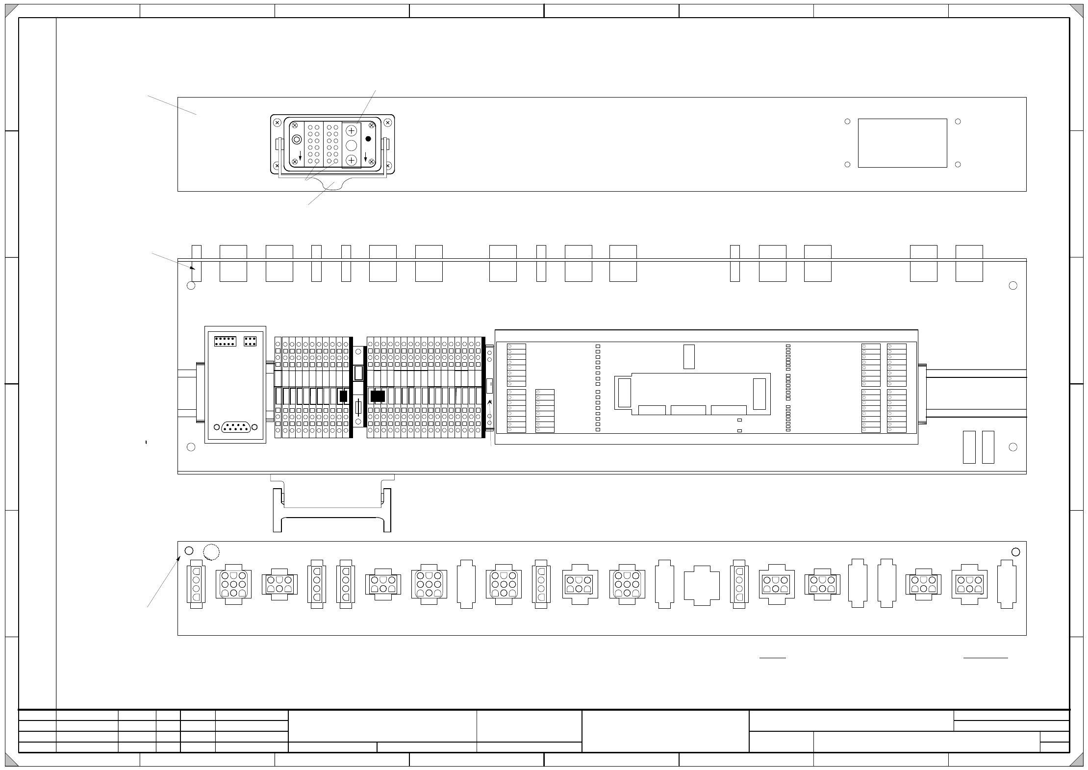
4 - 11
03050178-010201TD3 Hauptverteiler D1/D2
D1/D2 main distributor
Hauptverteiler
Main distributor
03050178-010201TD3
1
21.04.2006
Tuth
Gunadi
31.10.06
402857RS02
DT EA
SIPLACE D1/D2
Orig. Repl. by.Repl. f.
W
e
i
t
e
r
g
a
b
e
s
o
w
i
e
V
e
r
v
i
e
l
f
ä
l
t
i
g
u
n
g
d
i
e
s
e
r
U
n
t
e
r
l
a
g
e
,
V
e
r
w
e
r
t
u
n
g
u
n
d
M
i
t
t
e
i
l
u
n
g
i
h
r
e
s
I
n
h
a
l
t
s
n
i
c
h
t
g
e
s
t
a
t
t
e
t
,
s
o
w
e
i
t
n
i
c
h
t
a
u
s
d
r
ü
c
k
l
i
c
h
z
u
g
e
s
t
a
n
d
e
n
.
Z
u
w
i
d
e
r
h
a
n
d
l
u
n
g
e
n
v
e
r
p
f
l
i
c
h
t
e
n
z
u
S
c
h
a
d
e
n
e
r
s
a
t
z
.
A
l
l
e
R
e
c
h
t
e
v
o
r
b
e
h
a
l
t
e
n
,
i
n
s
b
e
s
o
n
d
e
r
e
f
ü
r
d
e
n
F
a
l
l
d
e
r
P
a
t
e
n
t
e
r
t
e
i
l
u
n
g
o
d
e
r
G
M
-
E
i
n
t
r
a
g
u
n
g
.
P
r
o
p
r
i
e
t
a
r
y
d
a
t
a
,
c
o
m
p
a
n
y
c
o
n
f
i
d
e
n
t
i
a
l
.
A
l
l
r
i
g
h
t
s
r
e
s
e
r
v
e
d
.
C
o
n
f
i
e
a
t
i
t
r
e
d
e
s
e
c
r
e
t
d
'
e
n
t
r
e
p
r
i
s
e
.
T
o
u
s
d
r
o
i
t
s
r
e
s
e
r
v
e
s
.
C
o
m
u
n
i
c
a
d
o
c
o
m
o
s
e
g
r
e
d
o
e
m
p
r
e
s
a
r
i
a
l
.
R
e
s
e
r
v
a
d
o
s
t
o
d
o
s
o
s
d
i
r
e
i
t
o
s
.
C
o
n
f
i
a
d
o
c
o
m
o
s
e
c
r
e
t
e
i
n
d
u
s
t
r
i
a
l
.
N
o
s
r
e
s
e
r
v
a
m
o
s
t
o
d
o
s
l
o
s
d
e
r
e
c
h
o
s
.
21 786543
21 786543
A
B
C
D
E
F
A
B
C
D
E
F
Date
Author
Checked
StandardNameModificationStat. Date
Sheet
Designer 9
Copyright reserved
SIEMENS AG
Item name / Benennung
of
Document No. /
Dokumentennummer:
C
1
4
3
2
1
8
7
6
5
1
0
9
1
4
1
5
1
6
1
7
1
8
1
9
2
0
2
1
2
2
2
3
2
4
2
5
2
6
2
7
2
8
R1
X2bf X3bf X4bf X25bf X7bf X6bf X10bf X9bf X16bf X22bf X11bf X17bf X18bf X19bf X20bf
DO0
DO1
DO2
DO3
DO4
DO5
DO6
DO7
X
7
q
b
DO8
DO9
DO10
DO11
DO12
DO13
DO14
DO15
X
8
q
b
1
2
3
4
5
6
7
8
1
2
3
4
5
6
7
8
P24
GND
X
9
q
b
1
2
3
4
5
6
7
8
P24
GND
P24
GND
P24
GND
DI0
DI1
DI2
DI3
DI4
DI5
DI6
DI7
X
3
q
b
DI8
DI9
DI10
DI11
DI12
DI13
DI14
DI15
X
4
q
b
1
2
3
4
5
6
7
8
1
2
3
4
5
6
7
8
VCC
GND
EGND
DI4_5V
DI5_5V
DI6_5V
DI7_5V
DI16
DI17
DI18
DI19
DI20
DI21
DI22
DI23
1
2
3
4
5
6
7
8
1
2
3
4
5
6
7
8
X
6
q
b
X
5
q
b
EGND
DO0
DO7
DO8
DO15
LEDs
X
1
0
q
b
DI0
DI7
DI8
DI16
DI15
DI23
LEDs
A1
(qb)
1
2
3
Pin1
C
* Hinweis
Folgende Etiketten muessen aufgeklebt werden :
A: Identifikationsschild
B: Pruefschild
C: Erdungsschild ( gn/ge )
* Please note
Fit the following labels:
A: identification label
B: inspection label
C: ground label ( gn/ye )
A
B
Erdungsloch
Ground hole
B
Pneumatikmodul
(Kontakt bei 1 und 3)
Pneumatic module
(Contact at 1 and 3)
Modul
Module
C
A
Teil 001
Part 001
Bügel
Bracket
Steckerbeschriftung auf der Kante
Schriftgrösse 4mm
Connector label on the edge
Font size: 4mm
X
4
0
0
X1bf
X5bf
X2bf X3bf X4bf X25bf X7bf X6bf X10bf X9bf X16bf X22bf
X11bf X17bf X18bf
X19bf X20bfX5bf
1
2
1
3
A
1
1
(qa)
A3
X1qa
X2qa X3qa
P
E
A2
(qe)
X
1
q
e
X
2
q
e
X4qe X5qe X3qe
OK
1-WIRE
FAIL
LEDs
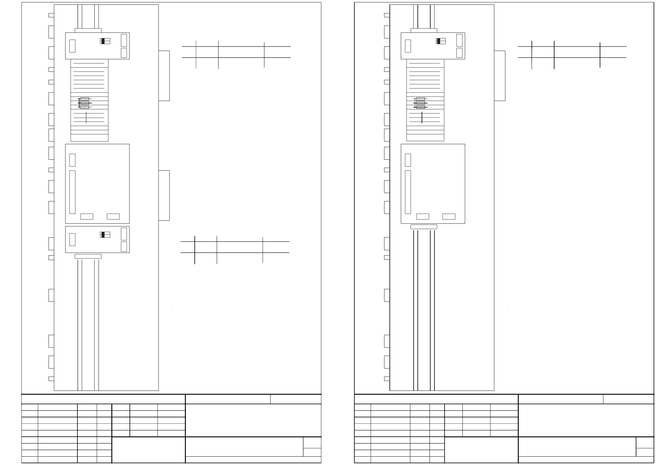
4 - 12
03053917-010201GD4 Maschinenschild Unterverteiler D1
Machine label, sub-distributor D1
03053918-010201GD4 Maschinenschild Unterverteiler D2
Machine label, sub-distributor D2
Maschinenschild Unterverteiler D1
Machine label sub-distributor D1
03053917-010201GD4
27.09.2006 Tuth
1
27.10.2006 Tuth
RS:02 ECP 403171 02.04.07 Krämer
Copyright reserved
SIEMENS AG
DT EA
P
r
o
p
r
i
e
t
a
r
y
d
a
t
a
,
c
o
m
p
a
n
y
c
o
n
f
i
d
e
n
t
i
a
l
.
A
l
l
r
i
g
h
t
s
r
e
s
e
r
v
e
d
.
C
o
n
f
i
e
a
t
i
t
r
e
d
e
s
e
c
r
e
t
d
'
e
n
t
r
e
p
r
i
s
e
.
T
o
u
s
d
r
o
i
t
s
r
e
s
e
r
v
e
s
.
C
o
m
u
n
i
c
a
d
o
c
o
m
o
s
e
g
r
e
d
o
e
m
p
r
e
s
a
r
i
a
l
.
R
e
s
e
r
v
a
d
o
s
t
o
d
o
s
o
s
d
i
r
e
i
t
o
s
.
C
o
n
f
i
a
d
o
c
o
m
o
s
e
c
r
e
t
e
i
n
d
u
s
t
r
i
a
l
.
N
o
s
r
e
s
e
r
v
a
m
o
s
t
o
d
o
s
l
o
s
d
e
r
e
c
h
o
s
.
Maßstab Format A4
Date
Author
Check.
Stand.
Name
Modification
Sheet
of
Date
(Dokument No. / Unterlagen Nr. (FS RS US SP F)
Item name / Benennung
NameStat.
W
e
i
t
e
r
g
a
b
e
s
o
w
i
e
V
e
r
v
i
e
l
f
ä
l
t
i
g
u
n
g
d
i
e
s
e
r
U
n
t
e
r
l
a
g
e
,
V
e
r
w
e
r
t
u
n
g
u
n
d
M
i
t
t
e
i
l
u
n
g
i
h
r
e
s
I
n
h
a
l
t
s
n
i
c
h
t
g
e
s
t
a
t
t
e
t
,
s
o
w
e
i
t
n
i
c
h
t
a
u
s
d
r
ü
c
k
l
i
c
h
z
u
g
e
s
t
a
n
d
e
n
.
Z
u
w
i
d
e
r
h
a
n
d
l
u
n
g
e
n
v
e
r
p
f
l
i
c
h
t
e
n
z
u
S
c
h
a
d
e
n
e
r
s
a
t
z
.
A
l
l
e
R
e
c
h
t
e
v
o
r
b
e
h
a
l
t
e
n
,
i
n
s
b
e
s
o
n
d
e
r
e
f
ü
r
d
e
n
F
a
l
l
d
e
r
P
a
t
e
n
t
e
r
t
e
i
l
u
n
g
o
d
e
r
G
M
-
E
i
n
t
r
a
g
u
n
g
.
1
PE
X
1
a
f
X2af
X3af
X25af
X7af
X10af
X4af
X5af
X6af
X9af
X16af
X11af
X12af
X18af
X19af
X20af
X22af
2
3
4
5
6
7
10
8
9
14
15
16
17
GND
P48V
Sub-distributor
11
12
+24V
13
PE
+5V
+24V (fuse 3.15A)
P50V_BE
S1 switch status on the CAN terminating module
WPC
S1.1 Adress 0 ON: adress 0
OFF: adress 0
Switch Function Coding Switch status
ON
S1.2 Adress 1 ONON: adress 1
OFF: adress 1
+24V (fuse 3.15A)
+24V (fuse 3.15A)
+24V
+24V
+24V
Vision DC/DC converter
X
1
r
c
X
2
r
c
X3rc X4rc
A1 (rc)
S1 switch status on the CAN terminating module
component table
S1.1 Adress 0 ON: adress 0
OFF: adress 0
Switch Function Coding Switch status
ON
S1.2 Adress 1 ONON: adress 1
OFF: adress 1
X
3
0
a
f
Relay K1
X8af
X15af
X
1
r
b
X
2
r
b
X
3
r
b
CAN-Bus terminator
component table
S1
A2 (rb)
OFFON
2
1
X
1
r
d
X
2
r
d
X
3
r
d
CAN-Bus terminator
WPC
S1
A3 (rd)
OFFON
2
1
1
Maschinenschild Unterverteiler D2
Machine label sub-distributor D2
03053918-010201GD4
27.10.2006 M. Gunadi
1
30.10.2006 M. Gunadi
RS:02 ECP 403102 04.02.07 Krämer
Copyright reserved
SIEMENS AG
DT EA
P
r
o
p
r
i
e
t
a
r
y
d
a
t
a
,
c
o
m
p
a
n
y
c
o
n
f
i
d
e
n
t
i
a
l
.
A
l
l
r
i
g
h
t
s
r
e
s
e
r
v
e
d
.
C
o
n
f
i
e
a
t
i
t
r
e
d
e
s
e
c
r
e
t
d
'
e
n
t
r
e
p
r
i
s
e
.
T
o
u
s
d
r
o
i
t
s
r
e
s
e
r
v
e
s
.
C
o
m
u
n
i
c
a
d
o
c
o
m
o
s
e
g
r
e
d
o
e
m
p
r
e
s
a
r
i
a
l
.
R
e
s
e
r
v
a
d
o
s
t
o
d
o
s
o
s
d
i
r
e
i
t
o
s
.
C
o
n
f
i
a
d
o
c
o
m
o
s
e
c
r
e
t
e
i
n
d
u
s
t
r
i
a
l
.
N
o
s
r
e
s
e
r
v
a
m
o
s
t
o
d
o
s
l
o
s
d
e
r
e
c
h
o
s
.
Maßstab Format A4
Date
Author
Check.
Stand.
Name
Modification
Sheet
of
Date
(Dokument No. / Unterlagen Nr. (FS RS US SP F)
Item name / Benennung
NameStat.
W
e
i
t
e
r
g
a
b
e
s
o
w
i
e
V
e
r
v
i
e
l
f
ä
l
t
i
g
u
n
g
d
i
e
s
e
r
U
n
t
e
r
l
a
g
e
,
V
e
r
w
e
r
t
u
n
g
u
n
d
M
i
t
t
e
i
l
u
n
g
i
h
r
e
s
I
n
h
a
l
t
s
n
i
c
h
t
g
e
s
t
a
t
t
e
t
,
s
o
w
e
i
t
n
i
c
h
t
a
u
s
d
r
ü
c
k
l
i
c
h
z
u
g
e
s
t
a
n
d
e
n
.
Z
u
w
i
d
e
r
h
a
n
d
l
u
n
g
e
n
v
e
r
p
f
l
i
c
h
t
e
n
z
u
S
c
h
a
d
e
n
e
r
s
a
t
z
.
A
l
l
e
R
e
c
h
t
e
v
o
r
b
e
h
a
l
t
e
n
,
i
n
s
b
e
s
o
n
d
e
r
e
f
ü
r
d
e
n
F
a
l
l
d
e
r
P
a
t
e
n
t
e
r
t
e
i
l
u
n
g
o
d
e
r
G
M
-
E
i
n
t
r
a
g
u
n
g
.
1
1
PE
X
1
a
f
X2af
X3af
X25af
X7af
X10af
X4af
X5af
X6af
X9af
X16af
X11af
X12af
X18af
X19af
X20af
X22af
2
3
4
5
6
7
10
8
9
14
15
16
17
GND
P48V
Sub-distributor
11
12
+24V
13
PE
+5V
+24V (fuse 3.15A)
P50V_BE
+24V (fuse 3.15A)
+24V (fuse 3.15A)
+24V
+24V
+24V
Vision DC/DC converter
X
1
r
c
X
2
r
c
X3rc X4rc
A1 (rc)
S1 switch status on the CAN terminating module
component table
S1.1 Adress 0 ON: adress 0
OFF: adress 0
Switch Function Coding Switch status
ON
S1.2 Adress 1 ONON: adress 1
OFF: adress 1
Relay K1
X8af
X15af
X
1
r
b
X
2
r
b
X
3
r
b
CAN-Bus terminator
component table
S1
A2 (rb)
OFFON
2
1