D系列电路图00194841-02_DC_SIPLACED12_DE+EN.pdf - 第92页
3 - 14 0304896 6-010301 LD3 Unterve rteiler D1 (Bl. 4 v. 4) Sub-dist ributor D1 (sh. 4 o f 4) Unter ver tei ler D 1 Sub-distr ibutor D1 03048966-010301LD3 4 10.05.2006 Tut h M. Gunadi 31.10.06 RS03 402857 SIPL ACE D1 Ori…
3 - 13
03048966-010301LD3 Unterverteiler D1 (Bl. 3 v. 4)
Sub-distributor D1 (sh. 3 of 4)
Unterverteiler D1
Sub-distributor D1
03048966-010301LD3
4
10.05.2006
Tuth M.
Gunadi31.10.06RS03 402857
SIPLACE D1
Orig. Repl. by.Repl. f.
W
e
i
t
e
r
g
a
b
e
s
o
w
i
e
V
e
r
v
i
e
l
f
ä
l
t
i
g
u
n
g
d
i
e
s
e
r
U
n
t
e
r
l
a
g
e
,
V
e
r
w
e
r
t
u
n
g
u
n
d
M
i
t
t
e
i
l
u
n
g
i
h
r
e
s
I
n
h
a
l
t
s
n
i
c
h
t
g
e
s
t
a
t
t
e
t
,
s
o
w
e
i
t
n
i
c
h
t
a
u
s
d
r
ü
c
k
l
i
c
h
z
u
g
e
s
t
a
n
d
e
n
.
Z
u
w
i
d
e
r
h
a
n
d
l
u
n
g
e
n
v
e
r
p
f
l
i
c
h
t
e
n
z
u
S
c
h
a
d
e
n
e
r
s
a
t
z
.
A
l
l
e
R
e
c
h
t
e
v
o
r
b
e
h
a
l
t
e
n
,
i
n
s
b
e
s
o
n
d
e
r
e
f
ü
r
d
e
n
F
a
l
l
d
e
r
P
a
t
e
n
t
e
r
t
e
i
l
u
n
g
o
d
e
r
G
M
-
E
i
n
t
r
a
g
u
n
g
.
P
r
o
p
r
i
e
t
a
r
y
d
a
t
a
,
c
o
m
p
a
n
y
c
o
n
f
i
d
e
n
t
i
a
l
.
A
l
l
r
i
g
h
t
s
r
e
s
e
r
v
e
d
.
C
o
n
f
i
e
a
t
i
t
r
e
d
e
s
e
c
r
e
t
d
'
e
n
t
r
e
p
r
i
s
e
.
T
o
u
s
d
r
o
i
t
s
r
e
s
e
r
v
e
s
.
C
o
m
u
n
i
c
a
d
o
c
o
m
o
s
e
g
r
e
d
o
e
m
p
r
e
s
a
r
i
a
l
.
R
e
s
e
r
v
a
d
o
s
t
o
d
o
s
o
s
d
i
r
e
i
t
o
s
.
C
o
n
f
i
a
d
o
c
o
m
o
s
e
c
r
e
t
e
i
n
d
u
s
t
r
i
a
l
.
N
o
s
r
e
s
e
r
v
a
m
o
s
t
o
d
o
s
l
o
s
d
e
r
e
c
h
o
s
.
21 786543
21 786543
A
B
C
D
E
F
A
B
C
D
E
F
Date
Author
Checked
StandardNameModificationStat. Date
Sheet
Designer 9
Copyright reserved
Siemens AG
DT EA
Item name / Benennung
of
Document No. /
Dokumentennummer:
2
3
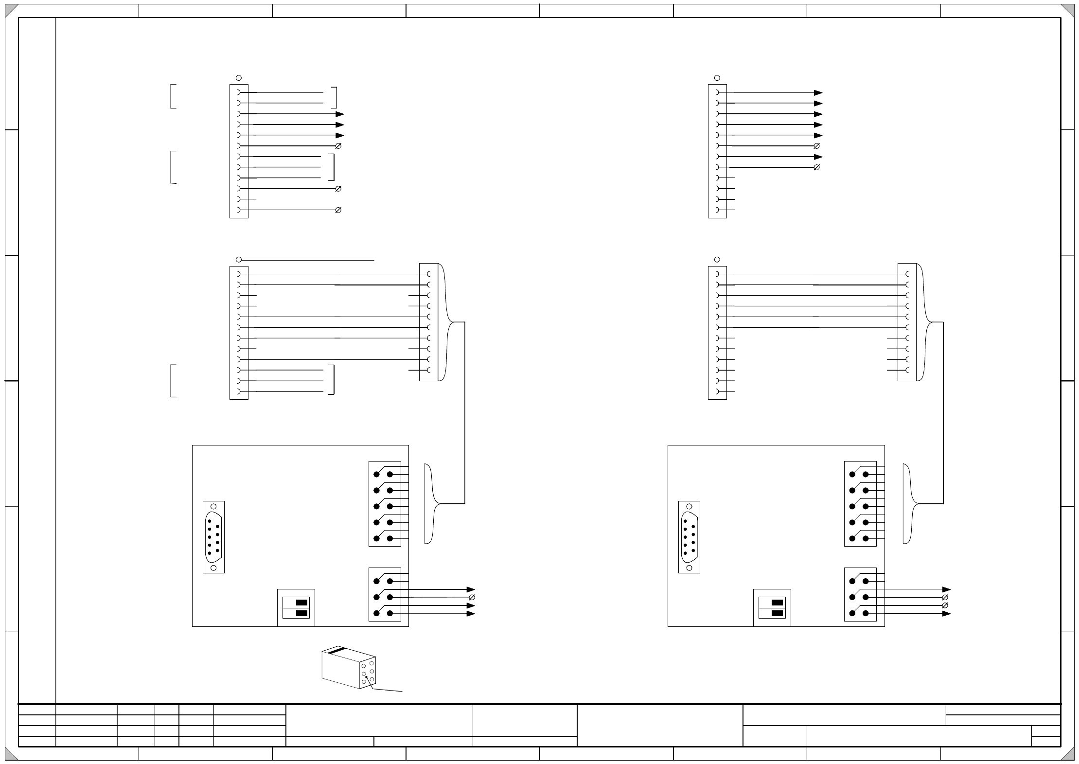
X1af
Modul A
A module
Modul B
B module
CompTableSocket
BeTischStecker /
CAN_L
CAN_H
Spare Reserve
Beilauflitze
Wire wh-og
BK (UL) / 0,5mm²
BK (UL) / 0,5mm²
Wire og
Wire wh-gn
Wire wh-bu
Wire wh-bn
Wire bu
Wire gn
Wire bn
Wire wh-og
Wire og
Wire wh-gn
Wire gn
Wire wh-bu
Wire bu
Wire wh-bn
Wire bn
Beilauflitze Splice Detection cable-03048972-xx
BK (UL) / 0,5mm²
Adr_0
S_Begin
M_Anfang
S_End M_Ende
X3rb_4
X16af_3
GND
BK (UL) / 1,0mm²
BK (UL) / 1,0mm²
BK (UL) / 1,0mm²
OG (UL) / 1,0mm²
B5
B4
B6
B3
B2
B1
B7
B8
B9
B10
B11
B12
X200_PE_b
WH (UL) / 1,0mm²
BU(UL) / 1,0mm²
Adr_1
Adr_GND
A5
A4
A6
A3
A2
A1
A7
A8
A9
A10
A11
A12
L_Begin
S_Anfang
L_End S_Ende
P50V_BE
nc.
CAN_GND
BK (UL) / 0,5mm²
X30af_A3
X200_15c (+24V)
X200_16d (+50V)
Splice-Detect
Splice-Detect
Option
Splice-Detect
Option
Splice-Detect
Option
BK (UL) / 0,5mm²
BK (UL) / 0,5mm²
Zu beachten ist, dass ...
die Zählfolge eines Locking-Clip-Steckers von der
Rückseite des Gehäuses betrachtet werden muss.
1
3
5
2
4
6
Kabel
cable
Please note that ...
that the numerical sequence of a locking clip plug
must be as viewed from the rear side of the casing.
Locking-Clip_Stecker X2rf und X3rf:
Locking clip plug X2rf and X3rf:
X2rb
2
3
4
5
1
7
10
Key
A2 (rb)
CAN-Bus Abschluss
BE-Tisch
CAN-Bus terminator
CompTable
Spare
Reserve
Spare Reserve
from CAN-Interface
(1MBit/s)
zu X1bf Modul B
to X1bf B module
X1rb
CAN-Bus Abschluss
Be-Tisch
CAN-Bus terminator
CompTable
A2 (rb)
SUBD
X3rb
X3af_8
X3af_2
Key
1
2
3
4
5
6
BK (UL) / 0,5mm²
BK (UL) / 0,5mm²
WH (UL) / 0,5mm²
BK (UL) / 0,5mm²
X200_7a (GND)
X1af_A5
10
9
X2rb
8
7
6
5
4
3
2
1
Key
X30af
Modul A
A module
Modul B
B module
WPC Socket
WPC Stecker /
CAN_L
CAN_H
Spare Reserve
BK (UL) / 0,5mm²
BK (UL) / 0,5mm²
Adr_0
WPC CAN terminating
X6af_2
X3af_9
BK (UL) / 1,0mm²
BK (UL) / 1,0mm²
BK (UL) / 1,0mm²
OG (UL) / 1,0mm²
B5
B4
B6
B3
B2
B1
B7
B8
B9
B10
B11
B12
X200_ PE_c
Adr_1
Adr_Com
A5
A4
A6
A3
A2
A1
A7
A8
A9
A10
A11
A12
L_Begin
S_Anfang
L_End S_Ende
CAN_GND
X1af_A4
X200_15d (+24V)
BK (UL) / 0,5mm²
BK (UL) / 0,5mm²
X2rd
2
7
5
3
1
4
10
Key
A3 (rd)
CAN-Bus Abschluss
WPC
CAN-Bus terminator
WPC
Spare
Reserve
Spare Reserve
BK (UL) / 1,0mm²
BK (UL) / 1,0mm²
X9af_2 (SSK D-1)
X9af_1 (SSK D-1)
(SSK D-1)
(SSK D-1)
from CAN-Interface
(1MBit/s)
zu X30bf Modul B
to X30bf B module
X1rd
CAN-Bus Abschluss
WPC
CAN-Bus terminator
WPC
A3 (rd)
SUBD
X3rd
X200_13c(24V)
X6af_3
Key
1
2
3
4
5
6
BK (UL) / 0,5mm²
BK (UL) / 0,5mm²
WH(UL) / 0,5mm²
OG (UL) / 0,5mm²
X200_7b (GND)
X30af_A5
10
9
X2rd
8
7
6
5
4
3
2
1
Key
X200_6a (GND)
WPC M_Anfang
WPC M_Ende
WPC CAN Terminierung
X3rd_4
BK (UL) / 1,0mm²
X200_12c (+24V)
OG (UL) / 1,0mm²
BK (UL) / 0,5mm²
Spare Reserve
Spare Reserve
Spare
Reserve
Cable-03048972-xx
Splice-Detect
Cable-03048972-xx
Splice-Detect
Cable-03048972-xx
BK (UL) / 0,5mm²
1
2
S1
ON
ON
Kodierung Be-Tisch
encoding CompTable
1
2
S1
ON
ON
Kodierung WPC
encoding WPC
3 - 14
03048966-010301LD3 Unterverteiler D1 (Bl. 4 v. 4)
Sub-distributor D1 (sh. 4 of 4)
Unterverteiler D1
Sub-distributor D1
03048966-010301LD3
4
10.05.2006
Tuth M.
Gunadi31.10.06RS03 402857
SIPLACE D1
Orig. Repl. by.Repl. f.
W
e
i
t
e
r
g
a
b
e
s
o
w
i
e
V
e
r
v
i
e
l
f
ä
l
t
i
g
u
n
g
d
i
e
s
e
r
U
n
t
e
r
l
a
g
e
,
V
e
r
w
e
r
t
u
n
g
u
n
d
M
i
t
t
e
i
l
u
n
g
i
h
r
e
s
I
n
h
a
l
t
s
n
i
c
h
t
g
e
s
t
a
t
t
e
t
,
s
o
w
e
i
t
n
i
c
h
t
a
u
s
d
r
ü
c
k
l
i
c
h
z
u
g
e
s
t
a
n
d
e
n
.
Z
u
w
i
d
e
r
h
a
n
d
l
u
n
g
e
n
v
e
r
p
f
l
i
c
h
t
e
n
z
u
S
c
h
a
d
e
n
e
r
s
a
t
z
.
A
l
l
e
R
e
c
h
t
e
v
o
r
b
e
h
a
l
t
e
n
,
i
n
s
b
e
s
o
n
d
e
r
e
f
ü
r
d
e
n
F
a
l
l
d
e
r
P
a
t
e
n
t
e
r
t
e
i
l
u
n
g
o
d
e
r
G
M
-
E
i
n
t
r
a
g
u
n
g
.
P
r
o
p
r
i
e
t
a
r
y
d
a
t
a
,
c
o
m
p
a
n
y
c
o
n
f
i
d
e
n
t
i
a
l
.
A
l
l
r
i
g
h
t
s
r
e
s
e
r
v
e
d
.
C
o
n
f
i
e
a
t
i
t
r
e
d
e
s
e
c
r
e
t
d
'
e
n
t
r
e
p
r
i
s
e
.
T
o
u
s
d
r
o
i
t
s
r
e
s
e
r
v
e
s
.
C
o
m
u
n
i
c
a
d
o
c
o
m
o
s
e
g
r
e
d
o
e
m
p
r
e
s
a
r
i
a
l
.
R
e
s
e
r
v
a
d
o
s
t
o
d
o
s
o
s
d
i
r
e
i
t
o
s
.
C
o
n
f
i
a
d
o
c
o
m
o
s
e
c
r
e
t
e
i
n
d
u
s
t
r
i
a
l
.
N
o
s
r
e
s
e
r
v
a
m
o
s
t
o
d
o
s
l
o
s
d
e
r
e
c
h
o
s
.
21 786543
21 786543
A
B
C
D
E
F
A
B
C
D
E
F
Date
Author
Checked
StandardNameModificationStat. Date
Sheet
Designer 9
Copyright reserved
Siemens AG
DT EA
Item name / Benennung
of
Document No. /
Dokumentennummer:
4
X1rc
X3rc
9
10
1
2
X4rc
9
10
1
2
1
2
3
5
84
1 14
2613
X2rc
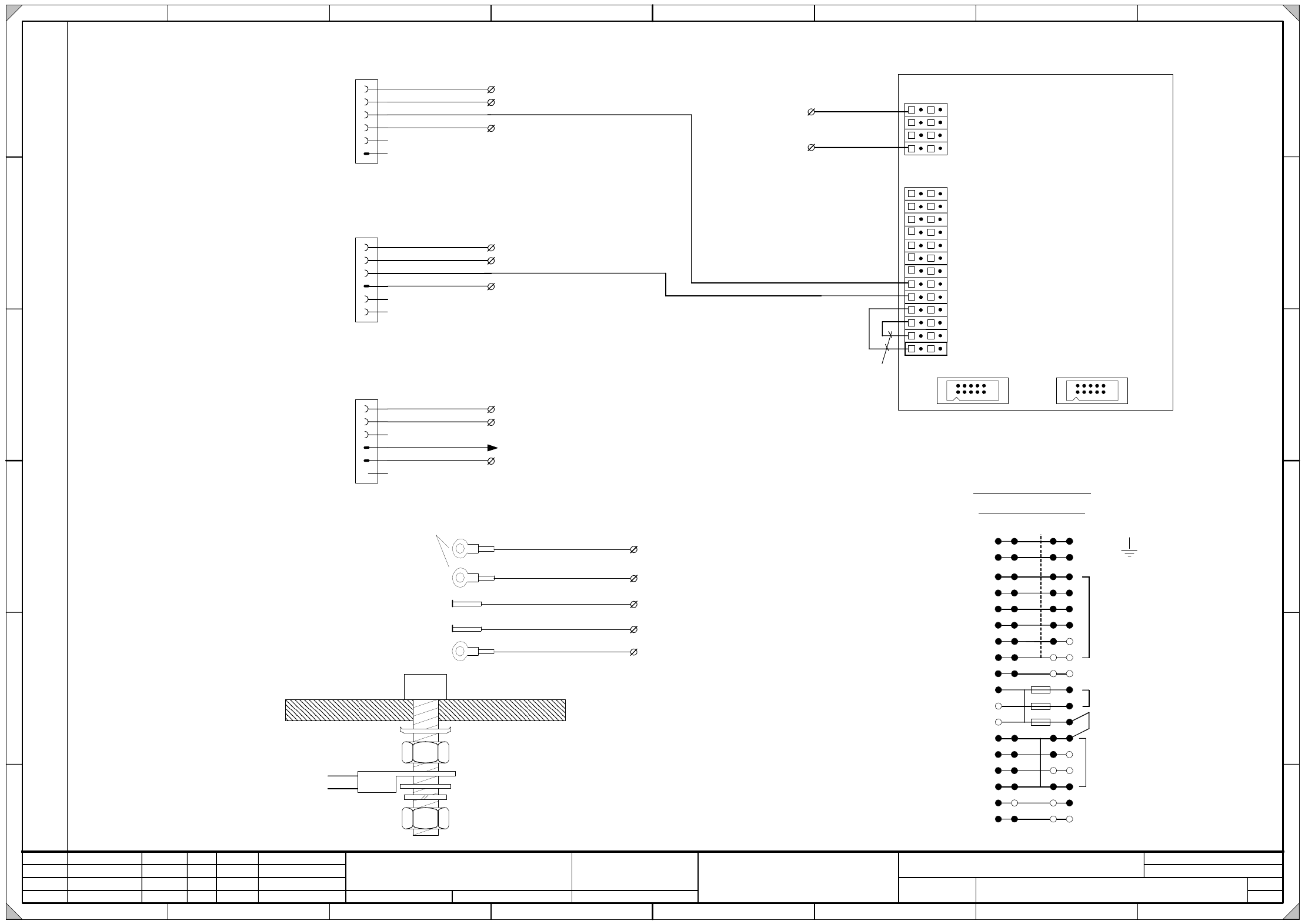
Vision DC/DC Wandler
vision DC/DC converter
03002280
A1 (rc)
10
9
11
12
4
6
7
X200_5d (GND)
WH (UL) / 1,5mm²
BK (UL) / 1,5mm²
X200_17b (P48V)
8
VI (UL) / 1,0mm²
VI (UL) / 1,0mm²
VI (UL) / 1,5mm²
X18af
1
2
3
4
5
6
Vision IC camera
Vision IC Kamera
res
GND
+24V
X19af
1
2
3
4
5
6
X20af
1
2
3
4
5
6
+24V
GND
X200_5b (GND)
X200_13a (24V)
BK (UL) / 1,0mm²
VL (UL) / 1,0mm²
VL (UL) / 1,0mm²
WH (UL) / 1,0mm²
WH (UL) / 1,0mm²
WH (UL) / 1,0mm²
OG (UL) / 1,0mm²
OG (UL) / 1,0mm²
OG (UL) / 1,0mm²
GND
WH (UL) / 1,0mm²
+42V
res
X200_2d (GND)
Vision IC camera
Vision IC Kamera
res
GND
+24V
GND
+42V
res
WH (UL) / 1,0mm²
X200_4d (GND)
X200_13b (24V)
X200_4c (GND)
X200_5c (GND)
PE
X200_14b (24V)
BK (UL) / 1,0mm²
Coplan modul
Koplan Modul
X6af_1
res
res
X200_1c (PE)
Ctrl_EmptyTapeC. St_Gurts.
GNYE (UL) / 2,5mm²
X200 terminal overview
Klemmenuebersicht X200
1
2
a
cb
+24V
5
4
6
7
8
9
10
13
14
15
11
12
16
PE
Erde
Ground
GND
d
+5V
P50V_BE
P48V
+24V (Schleppverteiler)
3
17
+24V (Einspeisung)
3,15AT
3,15AT
3,15AT
X200_PE_a
Ground Erdung PE Distributor
GNYE (UL) / 2,5mm²
X200_PE_b
GNYE (UL) / 2,5mm²
Ground Erdung PE X1af
PE
X200_PE_c
GNYE (UL) / 2,5mm²
Ground Erdung PE X30af
X200_PE_d
Ground machine frame Erdung PE Maschinenständer
GNYE (UL) / 2,5mm²
length=350mm
ring type cable lug M5
infeed
trailing cable distributor
X200_1d
Ground front plate Erdung PE Abdeckplatte
00336789-XX
Schraube / bolt
Kontaktscheibe / contact washer SN70093
Mutter DIN439 / nut DIN439
Kabelschuhring / annular cable lug
Mutter DIN439 / nut DIN439
Scheibe DIN125 / washer DIN125
Blech / plate
Federring DIN7980 / spring ring DIN7980
3 - 15
03050177-010301LD3 Unterverteiler D2 (Bl. 1 v. 4)
Sub-distributor D2 (sh. 1 of 4)
Unterverteiler D2
Sub-distributor D2
03050177-010301LD3
4
10.05.2006
Tuth M.
Gunadi31.10.06402857RS03
SIPLACE D2
Orig. Repl. by.Repl. f.
W
e
i
t
e
r
g
a
b
e
s
o
w
i
e
V
e
r
v
i
e
l
f
ä
l
t
i
g
u
n
g
d
i
e
s
e
r
U
n
t
e
r
l
a
g
e
,
V
e
r
w
e
r
t
u
n
g
u
n
d
M
i
t
t
e
i
l
u
n
g
i
h
r
e
s
I
n
h
a
l
t
s
n
i
c
h
t
g
e
s
t
a
t
t
e
t
,
s
o
w
e
i
t
n
i
c
h
t
a
u
s
d
r
ü
c
k
l
i
c
h
z
u
g
e
s
t
a
n
d
e
n
.
Z
u
w
i
d
e
r
h
a
n
d
l
u
n
g
e
n
v
e
r
p
f
l
i
c
h
t
e
n
z
u
S
c
h
a
d
e
n
e
r
s
a
t
z
.
A
l
l
e
R
e
c
h
t
e
v
o
r
b
e
h
a
l
t
e
n
,
i
n
s
b
e
s
o
n
d
e
r
e
f
ü
r
d
e
n
F
a
l
l
d
e
r
P
a
t
e
n
t
e
r
t
e
i
l
u
n
g
o
d
e
r
G
M
-
E
i
n
t
r
a
g
u
n
g
.
P
r
o
p
r
i
e
t
a
r
y
d
a
t
a
,
c
o
m
p
a
n
y
c
o
n
f
i
d
e
n
t
i
a
l
.
A
l
l
r
i
g
h
t
s
r
e
s
e
r
v
e
d
.
C
o
n
f
i
e
a
t
i
t
r
e
d
e
s
e
c
r
e
t
d
'
e
n
t
r
e
p
r
i
s
e
.
T
o
u
s
d
r
o
i
t
s
r
e
s
e
r
v
e
s
.
C
o
m
u
n
i
c
a
d
o
c
o
m
o
s
e
g
r
e
d
o
e
m
p
r
e
s
a
r
i
a
l
.
R
e
s
e
r
v
a
d
o
s
t
o
d
o
s
o
s
d
i
r
e
i
t
o
s
.
C
o
n
f
i
a
d
o
c
o
m
o
s
e
c
r
e
t
e
i
n
d
u
s
t
r
i
a
l
.
N
o
s
r
e
s
e
r
v
a
m
o
s
t
o
d
o
s
l
o
s
d
e
r
e
c
h
o
s
.
21 786543
21 786543
A
B
C
D
E
F
A
B
C
D
E
F
Date
Author
Checked
StandardNameModificationStat. Date
Sheet
Designer 9
Copyright reserved
Siemens AG
DT EA
Item name / Benennung
of
Document No. /
Dokumentennummer:
1
+24V
+24V
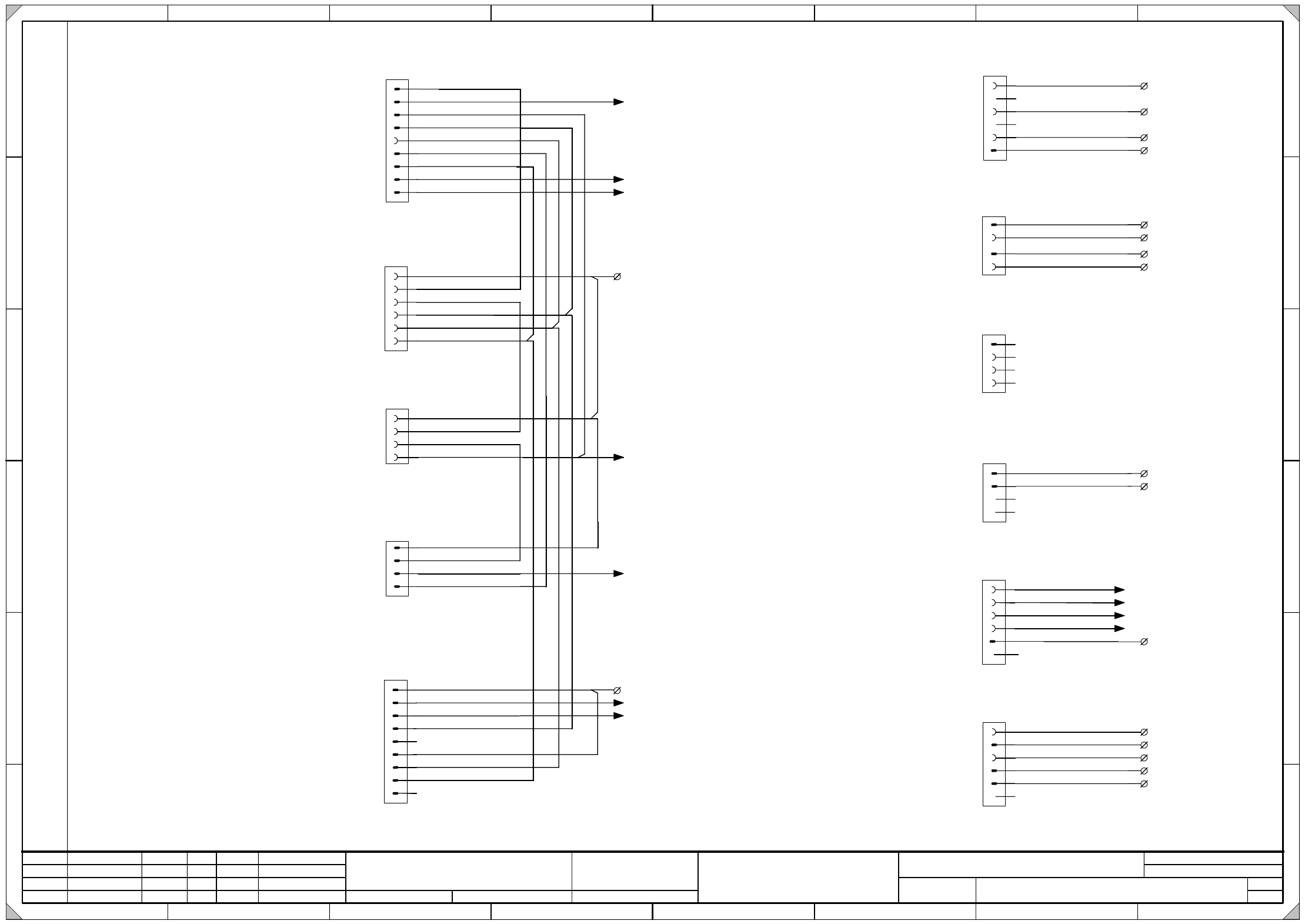
X4af
1
2
3
4
5
6
L_Begin
S_Anfang
S_hood
M_Haube
S_StartButton
M_StartTaste
S_StopButton M_StopTaste
L_End S_Ende
+24V
L_End
S_Ende
L_Begin S_Anfang
L_Begin
S_Anfang
L_End S_Ende
S_CompFlap
M_BeKlappe
StartStopButtonRight
EmergencyStopPCBInput
Start/StopTasteRechts
NOTHALT LPEingabe
CompFlap 1
BeKlappe 1
Option
Hood 1
Haube 1
X10af_2
X5af
1
4
2
3
2
1
3
4
X9af
1
2
3
4
X3af
5
4
6
3
2
1
7
8
9
S_hood M_Haube
S_StartButton
M_StartTaste
S_Emerg.StopButton
M_NotHaltTaste
S_CompFlap M_BeKlappe
S_CompEnd M_BeEnde
S_StopButton
M_StopTaste
L_End
S_Ende
Safety ring circuit
Sub distr.<>Main distr.
Ringl.Sicherheit
Untervert<>Hauptvert.
X3rb_1
X7af
2
3
4
5
1
Unregulated
DC voltages
ungeregelte
DC-Spannungen
N50V_BE
P50V_BE
N48V
P48V
X200_17a (P48V)
PPC33
SSK33
PPC34 SSK34
X200_16a (P50V_BE)
6
Spare Reserve
Spare Reserve
Spare Reserve
Spare Reserve
PPC
periphery
SSK
Peripherie
X200_4a (GND)
X200_5a (GND)
VI (UL) / 2,5mm²
BU (UL) / 2,5mm²
WH (UL) / 2,5mm²
WH (UL) / 2,5mm²
BK (UL) / 0,5mm²
BK (UL) / 0,5mm²
BK (UL) / 1,0mm²
BK (UL) / 1,0mm²
BK (UL) / 1,0mm²
BK (UL) / 1,0mm²
BK (UL) / 1,0mm²
OG (UL) / 1,0mm²
BK (UL) / 1,0mm²
BK (UL) / 1,0mm²
BK (UL) / 1,0mm²
BK (UL) / 1,0mm²
BK (UL) / 1,0mm²
OG (UL) / 1,0mm²
BK (UL) / 1,0mm²
BK (UL) / 1,0mm²
BK (UL) / 1,0mm²
BK (UL) / 1,0mm²
BK (UL) / 1,0mm²
BK (UL) / 1,0mm²
X15af
1
2
3
4
Fan 1-4 (gantry arm)
Luefter 1-4 (Portaltraeger)
+24V
GND
X200_12a (24V)
X200_2b (GND)
Spare
Reserve
Spare
Reserve
OG (UL) / 1,0mm²
WH (UL) / 1,0mm²
X25af
S_CompBegin M_BeAnfang
BK (UL) / 1,0mm²
X1af_A4
X200_14a (24V)
S_Emerg.StopButton M_NotHaltTa.
P24V
N24V
Regulated
DC voltages
geregelte
DC-Spannungen
N5V
P5V
1
2
3
4
5
6
X22af
X200_9a (24V)
X200_8a (5V)
X200_6b (GND)
X200_2a (GND)
Spare Reserve
OG (UL) / 2,5mm²
WH (UL) / 2,5mm²
WH (UL) / 2,5mm²
PK (UL) / 2,5mm²
OG (UL) / 1,0mm²
Spare Reserve
OG (UL) / 1,0mm²
X16af
1
2
3
4
5
6
7
8
9
+24V
L_End S_Ende
L_Begin
S_Anfang
S_Emerg.StopButton
M_NotHaltTaste
Start/Stop
Emergency Stop
Compr. air side
Start/Stop
Not-Halt
Druckluftseite
+24V
S_StartButton M_StartTaste
S_StopButton
M_StopTaste
OG (UL) / 1,0mm²
BK (UL) / 1,0mm²
BK (UL) / 1,0mm²
BK (UL) / 1,0mm²
BK (UL) / 1,0mm²
BK (UL) / 1,0mm²
X8af
1
2
3
4
Verteiler 1 +24V
infeed
gantry distributer
Speisung
Schlepp Verteiler
OG (UL) / 2,5mm²
WH (UL) / 2,5mm²
Verteiler 1 GND
X200_9d (24V)
X200_3c (GND)
Ground
PE
GNYE (UL) / 2,5mm²
X200_1a (PE)
BK (UL) / 1,0mm²
L_Begin S_Anfang
X12af
2
3
4
5
1
GND
Fault indicator 1
Stoerlampe 1
Fault indicator 2
Stoerlampe 2
Green indicator 2 Gruene Lampe 2
Green indicator 1 Gruene Lampe 1
X200_3a (GND)
Main fault indicator
Hauptstoerleuchte
6
BK (UL) / 1,0mm²
BK (UL) / 1,0mm²
BK (UL) / 1,0mm²
BK (UL) / 1,0mm²
WH (UL) / 1,0mm²
X6af_6
X6af_7
X6af_8
X6af_9
X10af_3
Spare Reserve
X1af_A3
X10af_4
X200_15a (24V)
Verteiler 2 +24V
Verteiler 2 GND
OG (UL) / 2,5mm²
WH (UL) / 2,5mm²
X200_10d (24V)
X200_3d (GND)
X3rb_2
Spare
Reserve