D系列电路图00194841-02_DC_SIPLACED12_DE+EN.pdf - 第33页
2 - ii SIPLACE D1/D2 Detailed Circuit Diagrams Folder Ausg abe 06/200 8 DE/EN Ed ition ZPP_D 1-020101L D3 Z -Achse, P&P-K opf, Porta l 1, SIPL ACE D1 (Bl. 2 v. 3) Z axis, P&P head , gantry 1, SIPLAC E D1 (sh. 2 o…
SIPLACE D1/D2 Detailed Circuit Diagrams Folder
Ausgabe 06/2008 DE/EN Edition
2 - i
2 Wirkschaltpläne / Detailed circuit diagrams
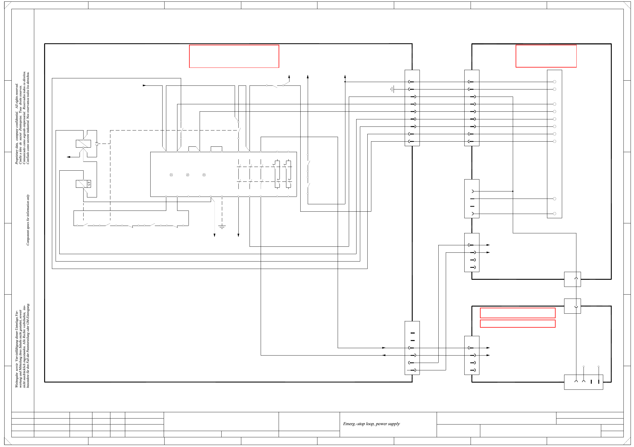
NH-020101LD3 NOT-HALT-Schleife, Stromversorgung (Bl. 1 v. 3)
Emergency stop loop, power supply (sh. 1 of 3) 1
NH-020101LD3 NOT-HALT-Schleife, Hauptverteiler (Bl. 2 v. 3)
Emergency stop loop, main distributor (sh. 2 of 3) 2
NH-020101LD3 NOT-HALT-Schleife, Unterverteiler (Bl. 3 v. 3)
Emergency stop loop, sub-distributor (sh. 3 of 3) 3
X01-020101LD3 X-Achse, Portal 1, SIPLACE D1, D2 (Bl. 1 v. 2)
X axis, gantry 1, SIPLACE D1, D2 (sh. 1 of 2) 4
X01-020101LD3 X-Achse, Portal 1, SIPLACE D1, D2 (Bl. 2 v. 2)
X axis, gantry 1, SIPLACE D1, D2 (sh. 2 of 2) 5
X02_D2-020101LD3 X-Achse, Portal 2, SIPLACE D2 (Bl. 1 v. 2)
X axis, gantry 2, SIPLACE D2 (sh. 1 of 2) 6
X02_D2-020101LD3 X-Achse, Portal 2, SIPLACE D2 (Bl. 2 v. 2)
X axis, gantry 2, SIPLACE D2 (sh. 2 of 2) 7
Y01-020101LD3 Y-Achse, Portal 1, SIPLACE D1, D2 (Bl. 1 v. 2)
Y axis, gantry 1, SIPLACE D1, D2 (sh. 1 of 2) 8
Y01-020101LD3 Y-Achse, Portal 1, SIPLACE D1, D2 (Bl. 2 v. 2)
Y axis, gantry 1, SIPLACE D1, D2 (sh. 2 of 2) 9
Y02_D2-020101LD3 Y-Achse, Portal 2, SIPLACE D2 (Bl. 1 v. 2)
Y axis, gantry 2, SIPLACE D2 (sh. 1 of 2) 10
Y02_D2-020101LD3 Y-Achse, Portal 2, SIPLACE D2 (Bl. 2 v. 2)
Y axis, gantry 2, SIPLACE D2 (sh. 2 of 2) 11
DR01_D1-020101LD3 Sternachse, C&P12-Kopf, Portal 1, SIPLACE D1
Star axis, C&P12 head, gantry 1, SIPLACE D1 12
DR01_D2-020101LD3 Sternachse, C&P12-Kopf, Portal 1, SIPLACE D2
Star axis, C&P12 head, gantry 1, SIPLACE D2 13
DR02_D2-020101LD3 Sternachse, C&P12-Kopf, Portal 2, SIPLACE D2
Star axis, C&P12 head, gantry 2, SIPLACE D2 14
Z01_D1-020101LD3 Z-Achse, C&P12-Kopf, Portal 1, SIPLACE D1
Z axis, C&P12 head, gantry 1, SIPLACE D1 15
Z01_D2-020101LD3 Z-Achse, C&P12-Kopf, Portal 1, SIPLACE D2
Z axis, C&P12 head, gantry 1, SIPLACE D2 16
Z02_D2-020101LD3 Z-Achse, C&P12-Kopf, Portal 2, SIPLACE D2
Z axis, C&P12 head, gantry 2, SIPLACE D2 17
DP01_D1-020101LD3 DP-Achse, C&P12-Kopf, Portal 1, SIPLACE D1
DP axis, C&P12 head, gantry 1, SIPLACE D1 18
DP01_D2-020101LD3 DP-Achse, C&P12-Kopf, Portal 1, SIPLACE D2
DP axis, C&P12 head, gantry 1, SIPLACE D2 19
DP02_D2-020101LD3 DP-Achse, C&P12-Kopf, Portal 2, SIPLACE D2
DP axis, C&P12 head, gantry 2, SIPLACE D2 20
ZM01-020101LD3 Zustelleinheiten, Blasluft, C&P12-Kopf, Portal 1, SIPLACE D1, D2
Adjustment units, forced air, C&P12 head, gantry 1, SIPLACE D1, D2 21
ZM02_D2-020101LD3 Zustelleinheiten, Blasluft, C&P12-Kopf, Portal 1, SIPLACE D2
Adjustment units, forced air, C&P12 head, gantry 1, SIPLACE D2 22
ZPP_D1-020101LD3 Z-Achse, P&P-Kopf, Portal 1, SIPLACE D1 (Bl. 1 v. 3)
Z axis, P&P head, gantry 1, SIPLACE D1 (sh. 1 of 3) 23
2 - ii
SIPLACE D1/D2 Detailed Circuit Diagrams Folder
Ausgabe 06/2008 DE/EN Edition
ZPP_D1-020101LD3 Z-Achse, P&P-Kopf, Portal 1, SIPLACE D1 (Bl. 2 v. 3)
Z axis, P&P head, gantry 1, SIPLACE D1 (sh. 2 of 3) 24
ZPP_D1-020101LD3 Z-Achse, P&P-Kopf, Portal 1, SIPLACE D1 (Bl. 3 v. 3)
Z axis, P&P head, gantry 1, SIPLACE D1 (sh. 3 of 3) 25
DPPP_D1-020101LD3 DP-Achse, P&P-Kopf, Portal 1, SIPLACE D1 (Bl. 1 v. 3)
DP axis, P&P head, gantry 1, SIPLACE D1 (sh. 1 of 3) 26
DPPP_D1-020101LD3 DP-Achse, P&P-Kopf, Portal 1, SIPLACE D1 (Bl. 2 v. 3)
DP axis, P&P head, gantry 1, SIPLACE D1 (sh. 2 of 3) 27
DPPP_D1-020101LD3 DP-Achse, P&P-Kopf, Portal 1, SIPLACE D1 (Bl. 3 v. 3)
DP axis, P&P head, gantry 1, SIPLACE D1 (sh. 3 of 3) 28
LPT-010201LD3 LP-Einfach/Doppeltransport, Transportsteuerung TSP-201 (Bl. 1 v. 11)
PCB single/dual conveyor, TSP 201 conveyor control (sh. 1 of 11) 29
LPT-010201LD3 LP-Einfach/Doppeltransport, Transportsteuerung TSP-201 (Bl. 2 v. 11)
PCB single/dual conveyor, TSP 201 conveyor control (sh. 2 of 11) 30
LPT-010201LD3 LP-Einfach/Doppeltransport, Umsetzplatine "Transport" (Bl. 3 v. 11)
PCB single/dual conveyor, conversion board "conveyor" (sh. 3 of 11) 31
LPT-010201LD3 LP-Einfach/Doppeltransport, Umsetzplatine "Transport" (Bl. 4 v. 11)
PCB single/dual conveyor, conversion board "conveyor" (sh. 4 of 11) 32
LPT-010201LD3 LP-Einfach/Doppeltransport, Umsetzplatine "Transport" (Bl. 5 v. 11)
PCB single/dual conveyor, conversion board "conveyor" (sh. 5 of 11) 33
LPT-010201LD3 LP-Einfach/Doppeltransport, Umsetzplatine "Transport" (Bl. 6 v. 11)
PCB single/dual conveyor, conversion board "conveyor" (sh. 6 of 11) 34
LPT-010201LD3 LP-Einfach/Doppeltransport, Umsetzplatine "Transportwange A" (Bl. 7 v. 11)
PCB single/dual conveyor, conversion board "conveyor rail A" (sh. 7 of 11) 35
LPT-010201LD3 LP-Einfach/Doppeltransport, Umsetzplatine "Transportwange B" (Bl. 8 v. 11)
PCB single/dual conveyor, conversion board "conveyor rail B" (sh. 8 of 11) 36
LPT-010201LD3 LP-Einfach/Doppeltransport, Umsetzplatine "Transportwange C" (Bl. 9 v. 11)
PCB single/dual conveyor, conversion board "conveyor rail C" (sh. 9 of 11) 37
LPT-010201LD3 LP-Einfach/Doppeltransport, Umsetzplatine "Transportwange D" (Bl. 10 v. 11)
PCB single/dual conveyor, conversion board "conveyor rail D" (sh. 10 of 11) 38
LPT-010201LD3 LP-Einfach/Doppeltransport, Umsetzplatine "Hubtisch",
Spuren 1+2 (Bl. 11 v. 11)
PCB single/dual conveyor, conversion board "lifting table",
tracks 1+2 (sh. 11 of 11) 39
BEW-010101LD3 Schnittstelle, BE-Wagen
Interface, CO trolley 40
GS-010101LD3 Gurtschneidgerät, Stellplatz 2, Hauptverteiler (Bl. 1 v. 2)
Tape cutter, location 2, main distributor (sh. 1 of 2) 41
GS-010101LD3 Gurtschneidgerät, Stellplatz 1, Unterverteiler, Hauptventil (Bl. 2 v. 2)
Tape cutter, location 1, sub- distributor, main valve (sh. 2 of 2) 42
PW-010101LD3 Pipettenwechsler
Nozzle changer 43
2 - 1
2 Wirkschaltpläne / Detailed circuit diagrams
NH-020101LD3 NOT-HALT-Schleife, Stromversorgung (Bl. 1 v. 3)
Emergency stop loop, power supply (sh. 1 of 3)
=
Date
Check.
Stand.
Author
Sheet
Orig. Repl. f. Repl. byNameDateModifiedStatus
Sh.
+
2
F
3
F
8
A
2
D
3
C
B
A
5
B
41
E
5
41
C
D
E
678
76
2.
1.
1.
01.04.08
01.04.08
01.04.08
26.09.2006
Hick
NH-020101LD3
1
3
Hick
Hick
Hick
Function st.
Product st.
Document st.
SIPLACE D1/D2
NOT-HALT-Schleife, Stromversorgung
CAD file : NH-020101LD3_SH01.DWG
Main distributor D1/D2
03050178 (sheet 2)
21b
25c
23c
24c
1d
28d
26c
X400
27d
BK
4
X9af
2
3
1
8
9
X12
6
7
5
4
1
2
3
WH+BN
GNYE
1
3
2
GN+YE
GY
PK
BU
(W1)
(W1)
(W1)
(W1)
(W2)
(W2)
(W1)
(W2)
(W2)
3P40V
RGP
S_Ready
S_ControlOn
Button ON
Axis power ON
Emerg.-stop
Emerg.-stop loop, begin
Pw_TapeCutter
Power supply
03039393
03041504
2
4
6
5
3
X13
1
n.u.
n.u.
1 (W1)
2 (W1)
1(W2)
2(W2)
PCC 34
PCC 33
n.u.
n.u.
n.u.
n.u.
03041505
BK
43
(SZ1)
K1.4
K23.4
2
1
(SZ23)(SZ4)
6
514 13
(Rel1)
K2.4
(SZ2)
2 1
Y33 Y34 Y43 Y44 A2 PE 24 3414 5242
X100 PE
N24V (ICLS.73)
Ctrl_XY (ICLS.72)
Y11A1 Y10 13Y21Y12 Y22 3323 41 51
PCC
3TK2825
Power Channel 1 Channel 2
-K1
43
12
SZ4
43
(SZ2)
4
(SZ2)
3
Rel1
SZ4
A1(+)
A2(-)
A1(+)
A2(-)
Di1
M (A1:M)
F12:2
P24V
43
K23.2
(SZ23)
1P40V
F8:2
BK
GNYE
BK
BK
BK
BK
BK
X6_1
3P40V
(PCB conveyor)
PCC 33
PCC 34
PCC 43
PCC 44
X9bf
1
2
3
4
n.u.
n.u.
X30af_A1 (sheet 3)
X30af_A2 (sheet 3)
SIPLACE D1 only
WPC4_Emergency stop loop
4
3
X11af
1
2
n.u.
WH
PK
BK
X200_8b (+5V)
X200_2c (GND)
Tape cutter
Location 1
X6af
1
1
X6bf
9-pole
9-pole
BK
03040343
Sub-distributor D1, 03048966
Sub-distributor D2, 03040177
Location 2
Tape cutter
Spare
3
4
1
2
X11bf
n.u.
BK
PK
WH
X22bf
2
9
8
7
4
6
5
3
1
S_ControlOn
S_Ready
Axis power ON
Button ON
Emerg.-stop
Emerg.-stop loop, begin
PE
Spare
3c
8c
GND
+5V
SIEMENS AG
Copyright reserved
DT EA
X8:6
K2.2
K2.1
See page 3-20
See page 3-3
See page 3-15
See page 3-11