D系列电路图00194841-02_DC_SIPLACED12_DE+EN.pdf - 第88页
3 - 10 0304028 4-010201 LD3 Kabel zum Unter verteiler (Bl. 4 v . 4) Cabl e to s ub-di str ibut or ( sh. 4 o f 4) 030402 84-0102 01LD 3 4 14.10.2005 Tu . Siemens AG Copyr ight r eserv ed SIPLAC E D1/D 2 Repl. by . Repl. f…
3 - 9
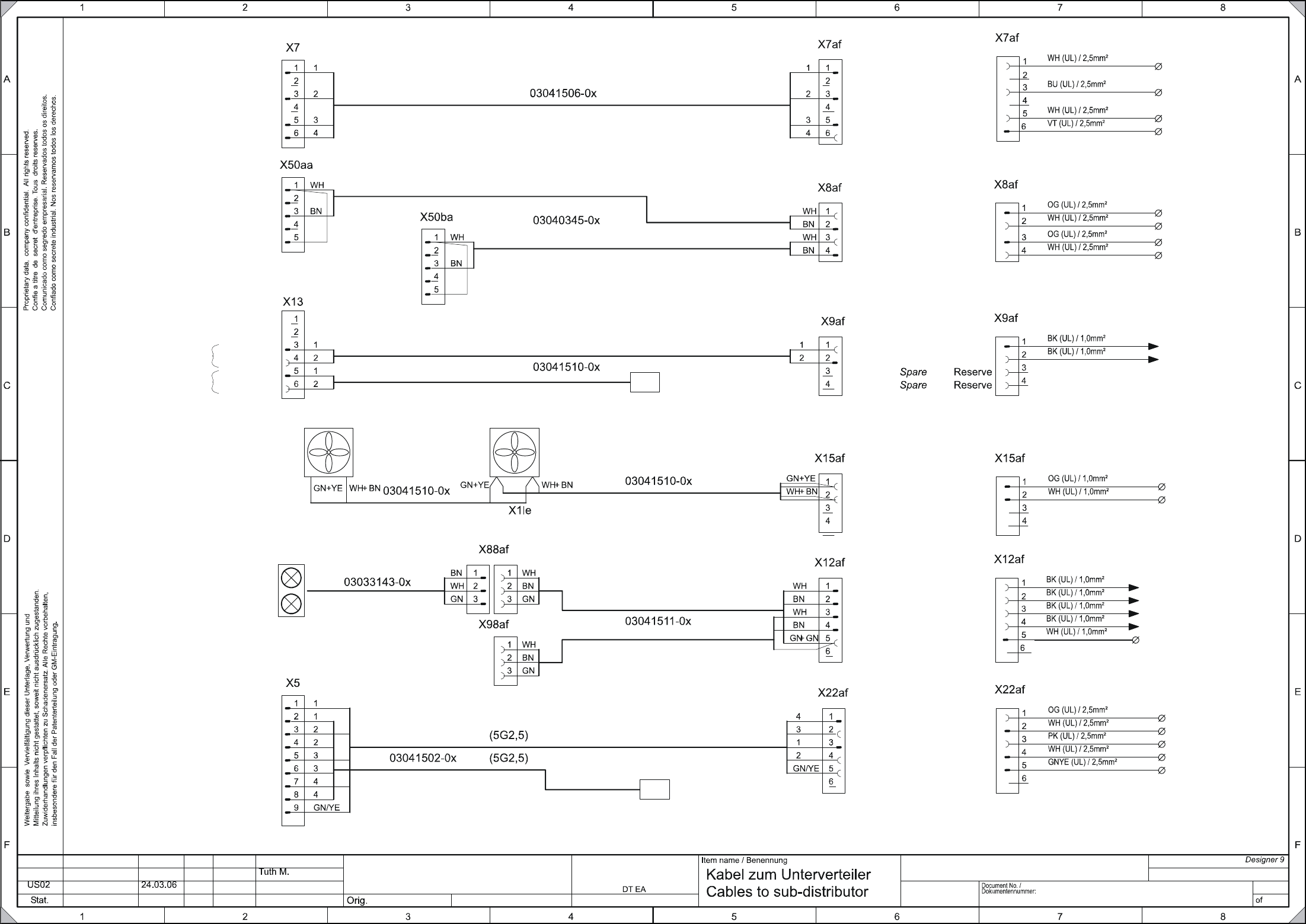
03040284-010201LD3 Kabel zum Unterverteiler (Bl. 3 v. 4)
Cable to sub-distributor (sh. 3 of 4)
03040284-010201LD3
4
14.10.2005
Tu.
Siemens AG
Copyright reserved
SIPLACE D1/D2
Repl. by.Repl. f.
Date
Author
Checked
StandardNameModification
Date
Sheet
3
Unregulated
DC voltages
power supply
ungeregelte
DC-Spannungen
Stromversorger
X
2
0
0
_
1
7
a
(
P
4
8
V
)
X
2
0
0
_
1
6
a
(
P
5
0
V
_
B
E
)
PPC
periphery
power supply
SSK
Peripherie
Stromversorger
X
2
0
0
_
4
a
(
G
N
D
)
X
2
0
0
_
5
a
(
G
N
D
)
Fan 1-2 (gantry arm)
Luefter 1-2 (Portaltraeger)
X
2
0
0
_
1
2
a
(
+
2
4
V
)
X
2
0
0
_
2
b
(
G
N
D
)
Regulated
DC voltages
power supply
geregelte
DC-Spannungen
Stromversorger
X
2
0
0
_
9
a
(
+
2
4
V
)
X
2
0
0
_
8
a
(
+
5
V
)
X
2
0
0
_
6
b
(
G
N
D
)
X
2
0
0
_
2
a
(
G
N
D
)
infeed
gantry distributer
Speisung
Schlepp Verteiler
X
2
0
0
_
9
d
(
+
2
4
V
)
X
2
0
0
_
3
c
(
G
N
D
)
X
2
0
0
_
1
a
(
P
E
)
X
2
0
0
_
3
a
(
G
N
D
)
Main fault indicator
Hauptstoerleuchte
X
6
a
f
_
6
X
6
a
f
_
7
X
6
a
f
_
8
X
6
a
f
_
9
X
3
0
a
f
_
A
1
X
3
0
a
f
_
A
2
(nur für D2 notwendig)
(required for D2 only)
W1
W2
X7bf
zum Hauptverteiler
(4x0,34)W2
(5x2,5)
(2x0,75)
(2x1,5)
W1
X9bf
zum Hauptverteiler
N50V_BE
P50V_BE
N48V
P48V
Res.
Res.
+24V
GND
+24V
SSK/PCC
SSK/PCC
SSK/PCC
SSK/PCC
N5V
P5V
P5V
N5V
N24V
N24V
P24V
P24V
PE
X
2
0
0
_
1
0
d
(
+
2
4
V
)
X
2
0
0
_
3
d
(
G
N
D
)
+24V
GND
+24V
(2x0,75)
X1me
W1
W2
(2x1,5)W2
N50V_BE
P50V_BE
N48V
P48V
SSK
SSK
Res.
Res.
+24V
GND
Res.
Res.
P24V
N24V
N5V
P5V
Res.
+24V
GND
PE
GND
Stoerlampe1
Stoerlampe2
GrueneLampe2
GrueneLampe1
+24V
GND
(3x0,34)W2
(3x0,34)W1
(4x0,34)W1
Steckerbelegung: siehe Blatt 2 beiden Kabeln zum Hauptverteiler
For the connector pin assignment see sheet 2 of the cables to main distributor
N50V_CO
P50V_CO
N48V
P48V
PCC
PCC
Spare
Spare
+24V
GND
Spare
Spare
P24V
N24V
N5V
P5V
Spare
PE
GND
FaultIndLamp1
FaultIndLamp2
GreenFaultIndLamp2
GreenFaultIndLamp1
(
P
5
0
V
_
C
O
)
N50V_CO
P50V_CO
N48V
P48V
Spare
Spare
1. Kreis
1 circuit
st
2. Kreis
2 circuit
nd
To main distributor
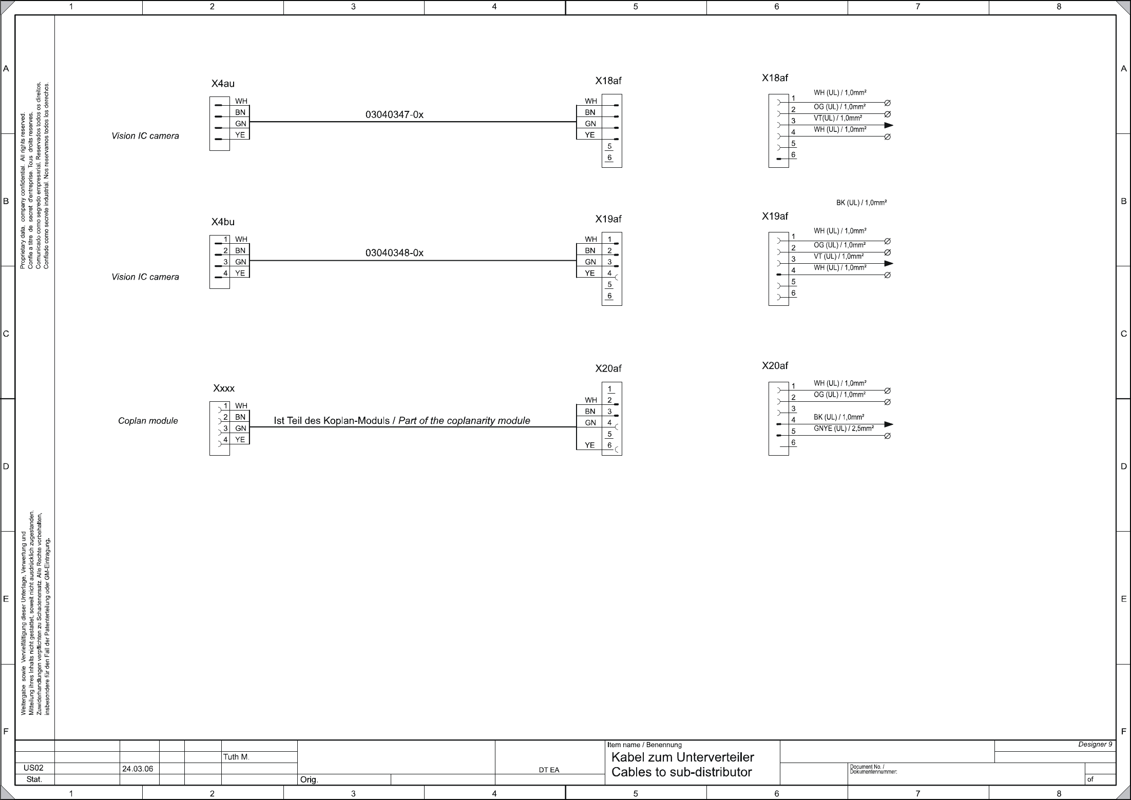
3 - 10
03040284-010201LD3 Kabel zum Unterverteiler (Bl. 4 v. 4)
Cable to sub-distributor (sh. 4 of 4)
03040284-010201LD3
4
14.10.2005
Tu.
Siemens AG
Copyright reserved
SIPLACE D1/D2
Repl. by.Repl. f.
Date
Author
Checked
StandardNameModification
Date
Sheet
4
Vision IC Kamera
res
GND
+24V
+24V
PE
X
2
0
0
_
5
b
(
G
N
D
)
X
2
0
0
_
1
3
a
(
+
2
4
V
)
GND
+42V
res
X
2
0
0
_
2
d
(
G
N
D
)
Vision IC Kamera
res
GND
+24V
GND
+42V
res
X
2
0
0
_
4
d
(
G
N
D
)
X
2
0
0
_
1
3
b
(
+
2
4
V
)
X
2
0
0
_
4
c
(
G
N
D
)
X
2
0
0
_
5
c
(
G
N
D
)
X
2
0
0
_
1
4
b
(
+
2
4
V
)
Koplan Modul
St_Gurts.
res
A
1
_
X
2
r
c
_
8
A
1
_
X
2
r
c
_
9
(4x0,75)
(4x0,75)
(4x0,75)
X
6
a
f
_
1
(
2
4
V
g
e
s
c
h
a
l
t
e
t
/
)
s
w
i
t
c
h
e
d
X
2
0
0
_
1
c
(
P
E
)
res
GND
Spare
GND
+24V
+24V
PE
GND
+42V
Spare
Spare
GND
+24V
GND
+42V
Spare
Ctrl_TapeCutter
Spare
Spare
GND
3 - 11
03048966-010301LD3 Unterverteiler D1 (Bl. 1 v. 4)
Sub-distributor D1 (sh. 1 of 4)
Unterverteiler D1
Sub-distributor D1
03048966-010301LD3
4
10.05.2006
Tuth M.
Gunadi31.10.06RS03 402857
SIPLACE D1
Orig. Repl. by.Repl. f.
W
e
i
t
e
r
g
a
b
e
s
o
w
i
e
V
e
r
v
i
e
l
f
ä
l
t
i
g
u
n
g
d
i
e
s
e
r
U
n
t
e
r
l
a
g
e
,
V
e
r
w
e
r
t
u
n
g
u
n
d
M
i
t
t
e
i
l
u
n
g
i
h
r
e
s
I
n
h
a
l
t
s
n
i
c
h
t
g
e
s
t
a
t
t
e
t
,
s
o
w
e
i
t
n
i
c
h
t
a
u
s
d
r
ü
c
k
l
i
c
h
z
u
g
e
s
t
a
n
d
e
n
.
Z
u
w
i
d
e
r
h
a
n
d
l
u
n
g
e
n
v
e
r
p
f
l
i
c
h
t
e
n
z
u
S
c
h
a
d
e
n
e
r
s
a
t
z
.
A
l
l
e
R
e
c
h
t
e
v
o
r
b
e
h
a
l
t
e
n
,
i
n
s
b
e
s
o
n
d
e
r
e
f
ü
r
d
e
n
F
a
l
l
d
e
r
P
a
t
e
n
t
e
r
t
e
i
l
u
n
g
o
d
e
r
G
M
-
E
i
n
t
r
a
g
u
n
g
.
P
r
o
p
r
i
e
t
a
r
y
d
a
t
a
,
c
o
m
p
a
n
y
c
o
n
f
i
d
e
n
t
i
a
l
.
A
l
l
r
i
g
h
t
s
r
e
s
e
r
v
e
d
.
C
o
n
f
i
e
a
t
i
t
r
e
d
e
s
e
c
r
e
t
d
'
e
n
t
r
e
p
r
i
s
e
.
T
o
u
s
d
r
o
i
t
s
r
e
s
e
r
v
e
s
.
C
o
m
u
n
i
c
a
d
o
c
o
m
o
s
e
g
r
e
d
o
e
m
p
r
e
s
a
r
i
a
l
.
R
e
s
e
r
v
a
d
o
s
t
o
d
o
s
o
s
d
i
r
e
i
t
o
s
.
C
o
n
f
i
a
d
o
c
o
m
o
s
e
c
r
e
t
e
i
n
d
u
s
t
r
i
a
l
.
N
o
s
r
e
s
e
r
v
a
m
o
s
t
o
d
o
s
l
o
s
d
e
r
e
c
h
o
s
.
21 786543
21 786543
A
B
C
D
E
F
A
B
C
D
E
F
Date
Author
Checked
StandardNameModificationStat. Date
Sheet
Designer 9
Copyright reserved
Siemens AG
DT EA
Item name / Benennung
of
Document No. /
Dokumentennummer:
1
+24V
+24V
X4af
1
2
3
4
5
6
L_Begin
S_Anfang
S_hood
M_Haube
S_StartButton
M_StartTaste
S_StopButton M_StopTaste
L_End S_Ende
+24V
L_End
S_Ende
L_Begin S_Anfang
L_Begin
S_Anfang
L_End S_Ende
S_CompFlap
M_BeKlappe
StartStopButtonRight
EmergencyStopPCBInput
Start/StopTasteRechts
NOTHALT LPEingabe
CompFlap 1
BeKlappe 1
Option
Hood 1
Haube 1
X10af_2
X5af
1
4
2
3
2
1
3
4
X9af
1
2
3
4
X3af
5
4
6
3
2
1
7
8
9
S_hood M_Haube
S_StartButton
M_StartTaste
S_Emerg.StopButton
M_NotHaltTaste
S_CompFlap M_BeKlappe
S_CompEnd M_BeEnde
S_StopButton
M_StopTaste
L_End
S_Ende
Safety ring circuit
Sub distr.<>Main distr.
Ringl.Sicherheit
Untervert<>Hauptvert.
X3rb_1
X7af
2
3
4
5
1
Unregulated
DC voltages
ungeregelte
DC-Spannungen
N50V_BE
P50V_BE
N48V
P48V
X200_17a (P48V)
PPC33
SSK33
PPC34 SSK34
X200_16a (P50V_BE)
6
Spare Reserve
Spare Reserve
Spare Reserve
Spare Reserve
PPC
periphery
SSK
Peripherie
X200_4a (GND)
X200_5a (GND)
VI (UL) / 2,5mm²
BU (UL) / 2,5mm²
WH (UL) / 2,5mm²
WH (UL) / 2,5mm²
BK (UL) / 0,5mm²
BK (UL) / 0,5mm²
BK (UL) / 1,0mm²
BK (UL) / 1,0mm²
BK (UL) / 1,0mm²
BK (UL) / 1,0mm²
BK (UL) / 1,0mm²
OG (UL) / 1,0mm²
BK (UL) / 1,0mm²
BK (UL) / 1,0mm²
BK (UL) / 1,0mm²
BK (UL) / 1,0mm²
BK (UL) / 1,0mm²
OG (UL) / 1,0mm²
BK (UL) / 1,0mm²
BK (UL) / 1,0mm²
BK (UL) / 1,0mm²
BK (UL) / 1,0mm²
BK (UL) / 1,0mm²
BK (UL) / 1,0mm²
X15af
1
2
3
4
Fan 1-4 (gantry arm)
Luefter 1-4 (Portaltraeger)
+24V
GND
X200_12a (24V)
X200_2b (GND)
Spare
Reserve
Spare
Reserve
OG (UL) / 1,0mm²
WH (UL) / 1,0mm²
X25af
S_CompBegin M_BeAnfang
BK (UL) / 1,0mm²
X30af_A4
X200_14a (24V)
S_Emerg.StopButton M_NotHaltTa.
P24V
N24V
Regulated
DC voltages
geregelte
DC-Spannungen
N5V
P5V
1
2
3
4
5
6
X22af
X200_9a (24V)
X200_8a (5V)
X200_6b (GND)
X200_2a (GND)
Spare Reserve
OG (UL) / 2,5mm²
WH (UL) / 2,5mm²
WH (UL) / 2,5mm²
PK (UL) / 2,5mm²
OG (UL) / 1,0mm²
Spare Reserve
OG (UL) / 1,0mm²
X16af
1
2
3
4
5
6
7
8
9
+24V
L_End S_Ende
L_Begin
S_Anfang
S_Emerg.StopButton
M_NotHaltTaste
Start/Stop
Emergency Stop
Compr. air side
Start/Stop
Not-Halt
Druckluftseite
+24V
S_StartButton M_StartTaste
S_StopButton
M_StopTaste
OG (UL) / 1,0mm²
BK (UL) / 1,0mm²
BK (UL) / 1,0mm²
BK (UL) / 1,0mm²
BK (UL) / 1,0mm²
BK (UL) / 1,0mm²
X8af
1
2
3
4
Verteiler 1 +24V
infeed
gantry distributer
Speisung
Schlepp Verteiler
OG (UL) / 2,5mm²
WH (UL) / 2,5mm²
Verteiler 1 GND
X200_9d (24V)
X200_3c (GND)
Ground
PE
GNYE (UL) / 2,5mm²
X200_1a (PE)
BK (UL) / 1,0mm²
L_Begin S_Anfang
X12af
2
3
4
5
1
GND
Fault indicator 1
Stoerlampe 1
Fault indicator 2
Stoerlampe 2
Green indicator 2 Gruene Lampe 2
Green indicator 1 Gruene Lampe 1
X200_3a (GND)
Main fault indicator
Hauptstoerleuchte
6
BK (UL) / 1,0mm²
BK (UL) / 1,0mm²
BK (UL) / 1,0mm²
BK (UL) / 1,0mm²
WH (UL) / 1,0mm²
X6af_6
X6af_7
X6af_8
X6af_9
X10af_3
Spare Reserve
X1af_A3
X10af_4
X200_15a (24V)
Verteiler 2 +24V
Verteiler 2 GND
OG (UL) / 2,5mm²
WH (UL) / 2,5mm²
X200_10d (24V)
X200_3d (GND)
X30af_A1
X30af_A2
X3rb_2
BK (UL) / 1,0mm²
BK (UL) / 1,0mm²