YSM20R_YSM20WR_Mainte_E.pdf - 第104页
3-43 3 Periodic maintenance items 7 Blow air into the spline air path. 1. Prepare the air blow tool and connect it to the air connector on the left or right of the machine. 2. Cover the portion where the air hose has bee…
3-42
3
Periodic maintenance items
5.1.2 FM head
1
Return all nozzles to nozzle
station.
1. Open the [Unit] - [Head] screen.
2. Select desired head unit from "Table
Select".
3. Press the [Nozzle Change] button.
4. Select "ALL" for "Head Number" and
select "Store Nozzle" for "Nozzle Type" on
the "Nozzle Change" screen.
5. Press the [OK] button to return all nozzles
to the nozzle station.
n
NOTE
If the machine is not equipped with a nozzle station,
press the emergency stop button and then remove the
nozzles manually.
e
2
Move the head unit.
1. Press the emergency stop button and
then open the machine safety cover.
2. If the machine is carriage type, detach
carriage to easily access to the head unit.
3. Move the head unit to a convenient
position for maintenance work and
remove all nozzles.
3
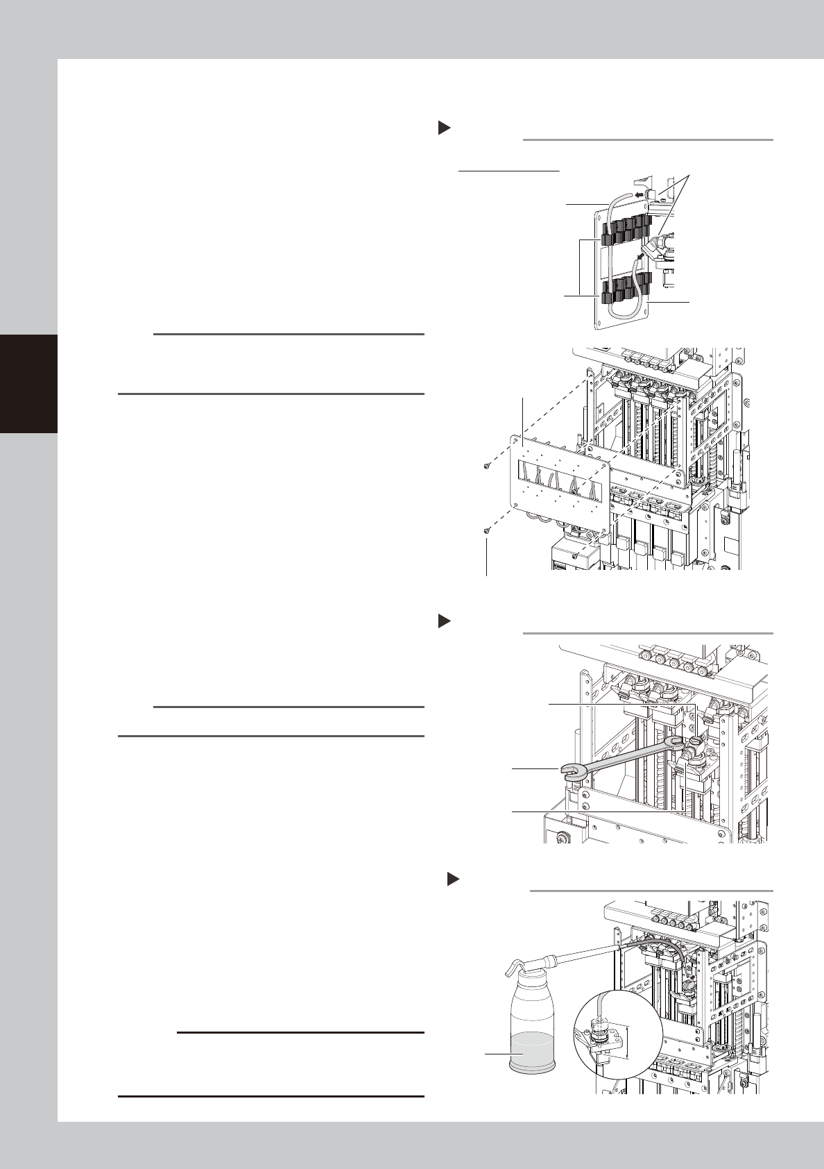
Disconnect the air hose and remove
the cover.
1. Remove screws on front cover with hex
wrench (3) holding the cover to avoid
falling.
2. Disconnect the air hose from the top and
bottom joints.
n
NOTE
Disconnect air hose attaching to the front cover.
4
Remove the maintenance bolt and
joint.
Use a flat-head screwdriver or wrench to
remove the maintenance bolt and joint.
5
Make the preparations for cleaning.
1. Place a paper cup or cloth under the
head to be cleaned.
2. Fill the cleaning kit with ethanol.
6
Clean the inside of spline shaft.
1. Insert the nozzle of the cleaning kit into
the cleaning hole of the spline shaft.
2. Pour ethanol into the spline shaft air path
to clean away dust and grime
c
CAUTION
Be sure to insert the nozzle tip 25 mm or more. If the
nozzle tip is inserted insufficiently, ethanol may flow into
the packing, etc.
Removing the front cover
Step 3
Rear side of front cover
Front cover
Front cover
Tube holder
Cover clamp bolt
Joint
Air hose
53358-KMK-00
Removing maintenance bolt and joint
Step 4
Maintenance bolt
wrench
Joint
53359-KMK-00
Cleaning the spline
Step 6
Ethanol
Cleaning kit
25 mm
or more
53360-KMK-00
3-43
3
Periodic maintenance items
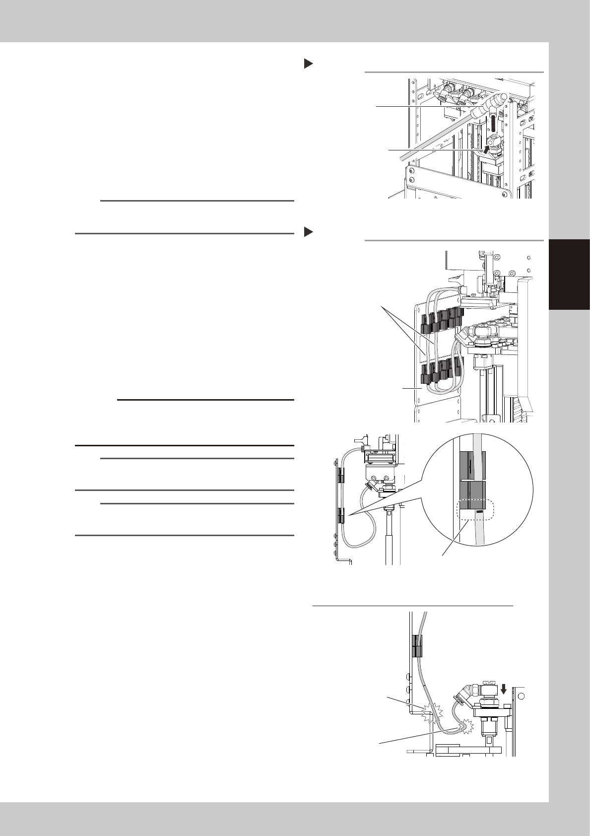
7
Blow air into the spline air path.
1. Prepare the air blow tool and connect it
to the air connector on the left or right of
the machine.
2. Cover the portion where the air hose has
been disconnected so that no air leaks,
and then blow the air into the inside of
the spline shaft.
3. Check that contaminant is no longer
discharged from the spline shaft tip.
n
NOTE
Repeat Step 6 and Step 7 until ethanol that flows out
from the spline shaft becomes clean.
8
Return the head to its original
state.
1. Install the maintenance bolt.
2. Attach the joint.
3. Connect the air hose.
4. Attach the front cover.
9
Check the air hose position.
Check that the air hoses are not crossing
and the air hose marking position is aligning
with the bottom of the tube holder.
c
CAUTION
If the air hoses are attached incorrectly, they are pulled
or bent when the head is lowered. This may damage the
air hoses or parts
.
TIP
The air hose marking position is 80 mm from the lower
end of the hose.
n
NOTE
If removed nozzles manually from the head, return
them to the original position of the head.
Blowing the air path
Step 7
Air blow tool
Push this portion
with finger.
53361-KMK-00
Checking the air hose attaching state
Step 9
Do not cross air hoses.
Make sure that air hose marking position
is aligning with bottom of tube holder.
Front cover
Incorrect attachment of air hoses (when head is lowered)
Air hose damage by hitting
Bending of air hose
53362-KMK-00
3-44
3
Periodic maintenance items
5.2 Inspecting conveyor belt and cleaning guide
Inspect the conveyor belt for wear. As the belt wears away, slippages may occur that prevent securely
conveying the boards. It is therefore necessary to make periodic checks for wear of the conveyor belt.
Additionally, if belt wear debris accumulate on the light receiving surface of the conveyor sensor, troubles such
as incorrect board detection may occur. If belt wear debris accumulate in the belt guide or pulley periphery,
the belt may be fixed.
YSM20R/YSM20WR has following 4 types of conveyor. The position of tensioner (pulley bracket/pulley) and
belt tension standard are different among 3 types.
• YSM20R Dual-stage type
• YSM20R Single-lane type
• YSM20WR Dual-lane type
• YSM20WR Single-lane type (for transferring heavy board)
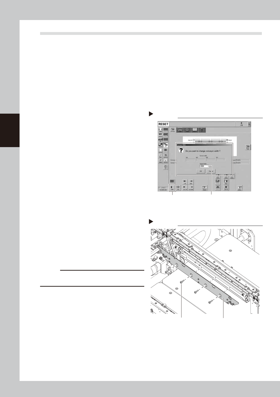
1
Change the conveyor width to a
convenient width for maintenance
work.
1. Press the [Width] button to display the
"Conveyor Width" screen.
2. In the "Target Width" box, enter a width
wide enough (about 200 mm) for using
tool (hex wrench) and press [OK] button.
The conveyor is changed to the specified
width.
2
Prepare for work.
e
1. Take off all accessories susceptible to the
magnetic fields, such as a wristwatch
and/or magnetic ID card.
2. Press the emergency stop button and
then open the machine safety cover.
3. If the machine is carriage type, detach
carriage to easily access to the conveyor.
4. Place a square cloth on the push-up
plate.
3
Detach the board clamp plates.
Use a hex wrench (3) to remove the 4 board
clamp bolts. Then remove the board clamp
plate.
c
CAUTION
Do not remove any bolts other than the 4 bolts shown in
the figure on the right.
Changing the conveyor width
Step 1
[Width] button Enter width that tool can be entered.
(about 200 mm)
54304-KMK-00
Detaching board clamp plate
Step 3
Board clamp plateMounting bolt
53363-KMK-00