YSM20R_YSM20WR_Mainte_E.pdf - 第83页
3-22 3 Periodic maintenance items 3.3 Operation check of blow valves for heads/cleaning P erform the operation check of v alves of head unit. T he valves of head unit include 2 types. The blo w valv e blows per head. The…
3-21
3
Periodic maintenance items
3.2 Checking ejector vacuum level
Check the ejector vacuum level of each head.
If the vacuum level does not reach at the specified level, it may be required to replace the ejector bit or valve.
Replace them referring to "6.1 Replacing the ejector bit" in chapter 3 or "3.1 HM head: Replacing valves" and
"3.2 FM head: Replacing valves" in chapter 6.
n
Example: HM head unit
e
1
Move head unit forward.
1. Press the emergency stop button and
then open the machine safety cover. If
the machine is carriage type, detach
carriage to easily access to the head unit.
2. Move the head unit to convenient
position for maintenance work.
2
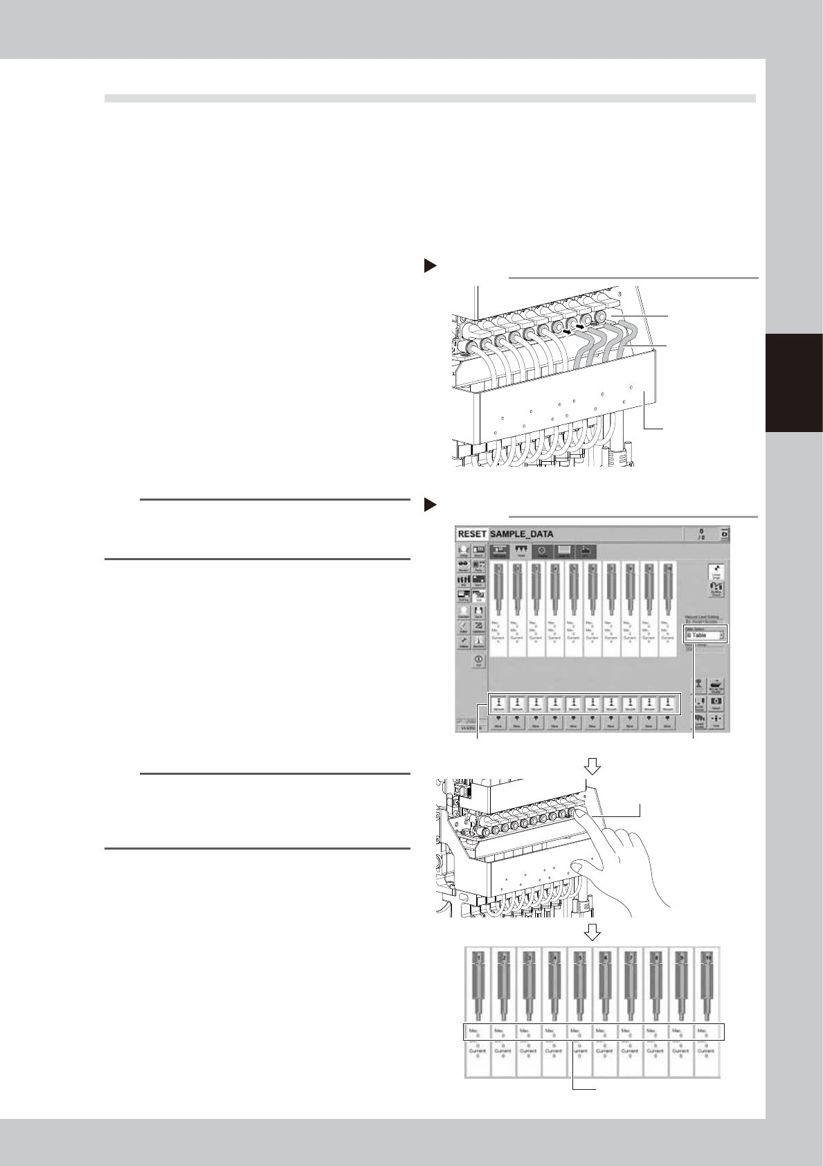
Disconnect air hoses from upper
air joints.
Disconnect all air hoses from upper air joints.
Do not disconnect air hoses from lower air
joints.
n
NOTE
Air hoses are connected to the holders on rear of front
cover of head unit. Make sure that air hoses will not
come off the holders.
3
Check vacuum level of each head.
1. Open [Unit] - [Head] screen.
2. Select desired head unit from "Table
Select".
3. Press the [Vacuum] buttons of all heads.
4. Cover the air joint with finger.
5. The vacuum level when sealed appears
in "Max" at the center of the screen.
Check that the measurement reference
value when sealed is "190" or more.
TIP
When the vacuum level does not reach at the
measurement reference value, review the air path
(ejector/valve) of the head. Then clean or replace it as
needed.
4
Return air hoses to the original
positions.
Disconnecting air hoses
Step 2
Air hose
Air joint
Head unit front cover
53397-KMK-00
Checking vacuum level
Step 3
Press [Vacuum] buttons of each head.
Check “Max” vacuum levels.
Cover air joint with finger.
Table Select
54312-KMK-00
3-22
3
Periodic maintenance items
3.3 Operation check of blow valves for heads/cleaning
Perform the operation check of valves of head unit.
The valves of head unit include 2 types. The blow valve blows per head. The blow valve for cleaning blows
strongly to clean the inside of the shaft. When the valve operation is unstable, it needs to be replaced. See
"3.1 HM head: Replacing valves"and "3.2 FM head: Replacing valves"in chapter 6 to replace valve.
c
CAUTION
As the blow valve for cleaning exhausts strong air, make sure to remove nozzles before cleaning with air blow.
If not, nozzles come off from the head and they may be damaged or lost.
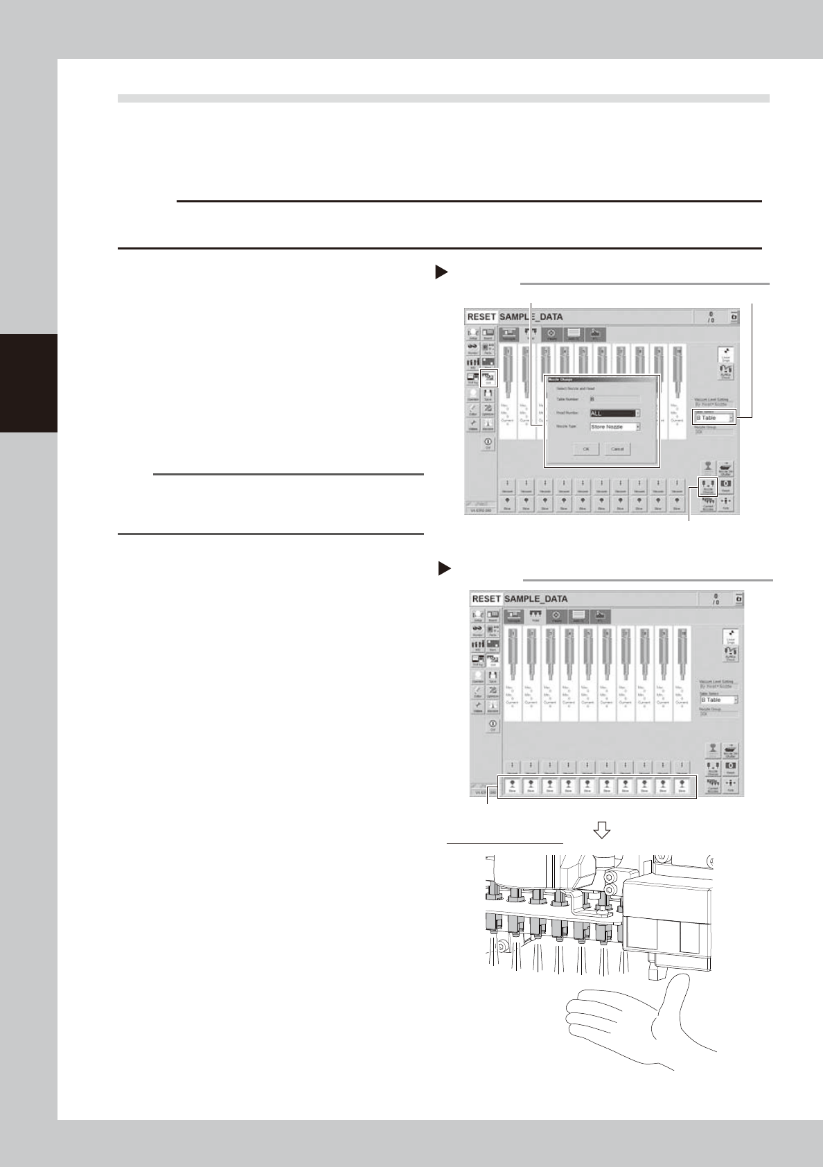
1
Remove nozzles from all heads.
1. Open [Unit] - [Head] screen.
2. Select desired head unit from "Table
Select".
3. Press the [Nozzle Change] button.
4. Select "ALL" for Head Number and select
"Store nozzle" for Nozzle type on "Nozzle
Change" screen.
5. Pressing the [OK] button stores nozzles of
all heads to the nozzle station.
n
NOTE
If the nozzle station is not equipped with the machine,
open the machine safety cover and remove nozzles
manually.
e
2
Move head unit forward.
1. Press the emergency stop button and
then open the machine safety cover.
2. If the machine is carriage type, detach
carriage to easily access to the head unit.
3. Move the head unit to convenient
position for maintenance work.
3
Air blow each head.
Open [Unit] - [Head] screen and press [Blow]
buttons of all heads.
4
Check blow operation.
Place a hand under each head to check
that air blows uniformly from all heads. If
light air blows compare to other heads or air
does not blow, the valve needs to be
replaced.
See "3.1 HM head: Replacing valves" and
"3.2 FM head: Replacing valves" in chapter 6
to replace valve.
Checking blow operation
Step 3,4
Checking air blow of heads
Press [Blow] buttons of heads.
54314-KMK-00
Storing nozzles
Step 1
Head Number: “ALL” / Nozzle type: “Store Nozzle”
[Nozzle Change] button
Table Select
54313-KMK-00
3-23
3
Periodic maintenance items
5
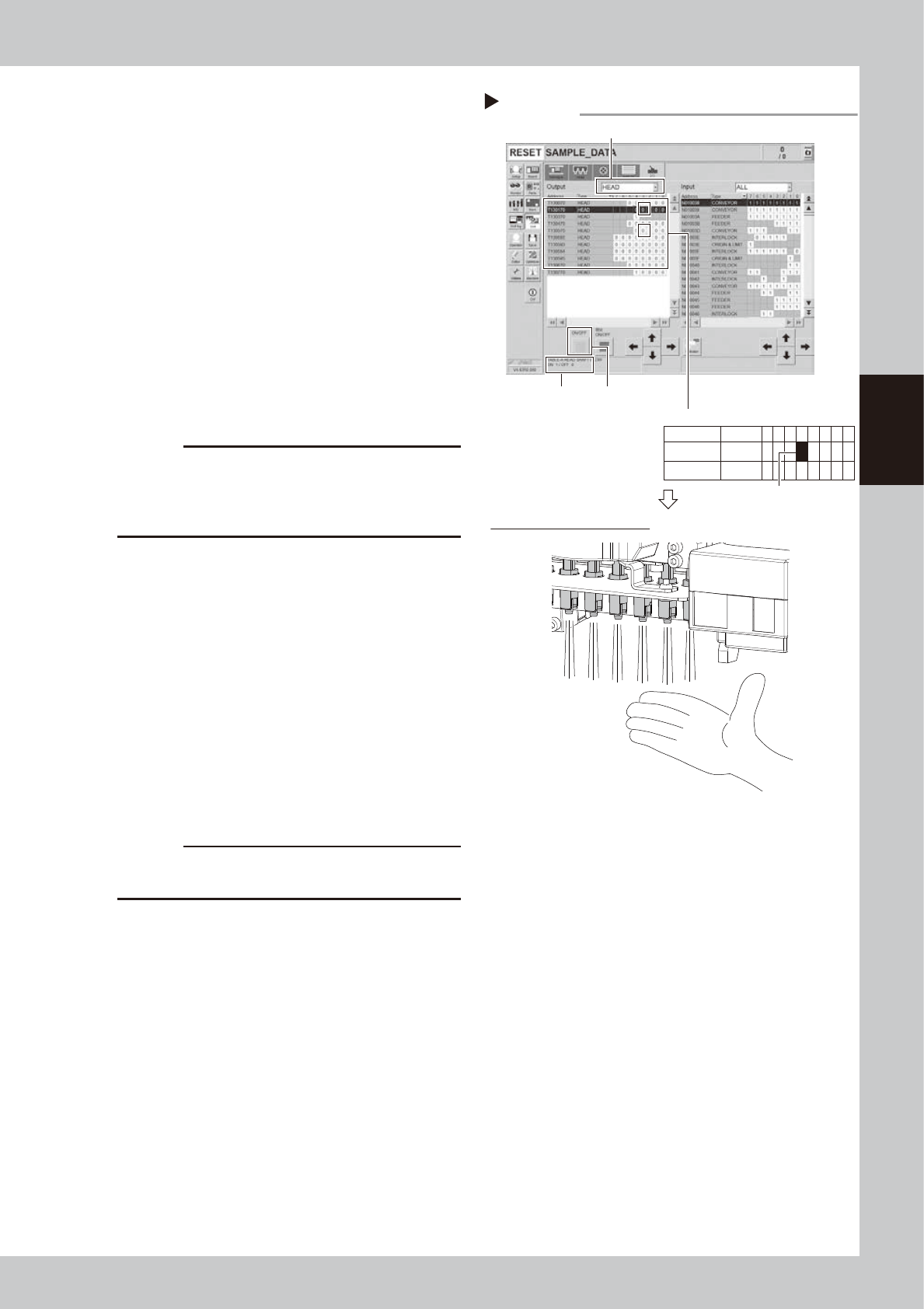
Operate blow valve for cleaning.
1. Open [Unit] - [I/O] screen.
2. Select "HEAD" from "Output" drop-down
list.
3. Select the address of blow valve for
cleaning.
n
Address of blow valve for cleaning
Table A: T1301704
Table B: T1305704
Select the address and check the
description on bottom left of the screen.
4. Recheck that all nozzles of the relevant
head unit are removed.
5. Blow valve for cleaning operates by
pressing [ON/OFF] button once.
(Address: 0 to 1)
c
CAUTION
Make sure to recheck that all nozzles of the relevant
head unit are removed before operating blow valve for
cleaning. If not, nozzles come off from the head and
they may be damaged or lost.
6
Check the condition of blow valve
for cleaning.
1. Place a hand under each head to check
that air blows stronger than Step 4.
2. Press [ON/OFF] button on [Unit] - [I/O]
screen again. The address changes from
1 to 0 and blow valve for cleaning closes.
3. Check that air from head is lighter.
If the strength of air from head does not
change even after operating the blow valve
for cleaning, it needs to be replaced.
See "3.1 HM head: Replacing valves" and
"3.2 FM head: Replacing valves" in chapter 6
to replace valve.
c
CAUTION
Make sure to wear safety goggles as cleaning air may
strike face.
7
Stop the blowing.
Press the [Blow] buttons of all heads on [Unit]
- [I/O] screen to stop the blowing.
8
Return nozzles to the original
position.
When the nozzles were removed from the
head manually, return them to the original
heads.
Checking the blowing
Step 5,6
Checking cleaning blow of heads
[ON/OFF] button
Select “HEAD” from “Output”.
Select address.
Address
description
Example: T1301704
Address
T130170
T130570
Type
HEAD
HEAD
7 6 5
0
0
4
0
0
3
0
0
2
0
0
1
0
0
0
0
0
54315-KMK-00