YSM20R_YSM20WR_Mainte_E.pdf - 第80页
3-19 3 Periodic maintenance items 2.3 Conveyor 2.3.1 Checking conveyor sensor condition and operation T his machine uses a transmission type fiber sensor as the conv eyor sensor . As the convey or width changes, the dist…
3-18
3
Periodic maintenance items
7
Perform a warm-up.
1. Remove the square cloth.
2. Close the machine safety cover and
cancel the emergency stop. Detach the
carriage if the machine is carriage type.
e
3. Open the Warm-up screen, and perform
the warm-up operation for approximately
8 minutes.
4. After stopping warming up, press the
emergency stop button and then open
the machine safety cover.
5. Wipe the grease accumulated on the
guide end surface.
c
CAUTION
Repeat Step 7 until grease accumulations no longer
occur. Beginning production with grease accumulations
present could cause the grease to spatter.
8
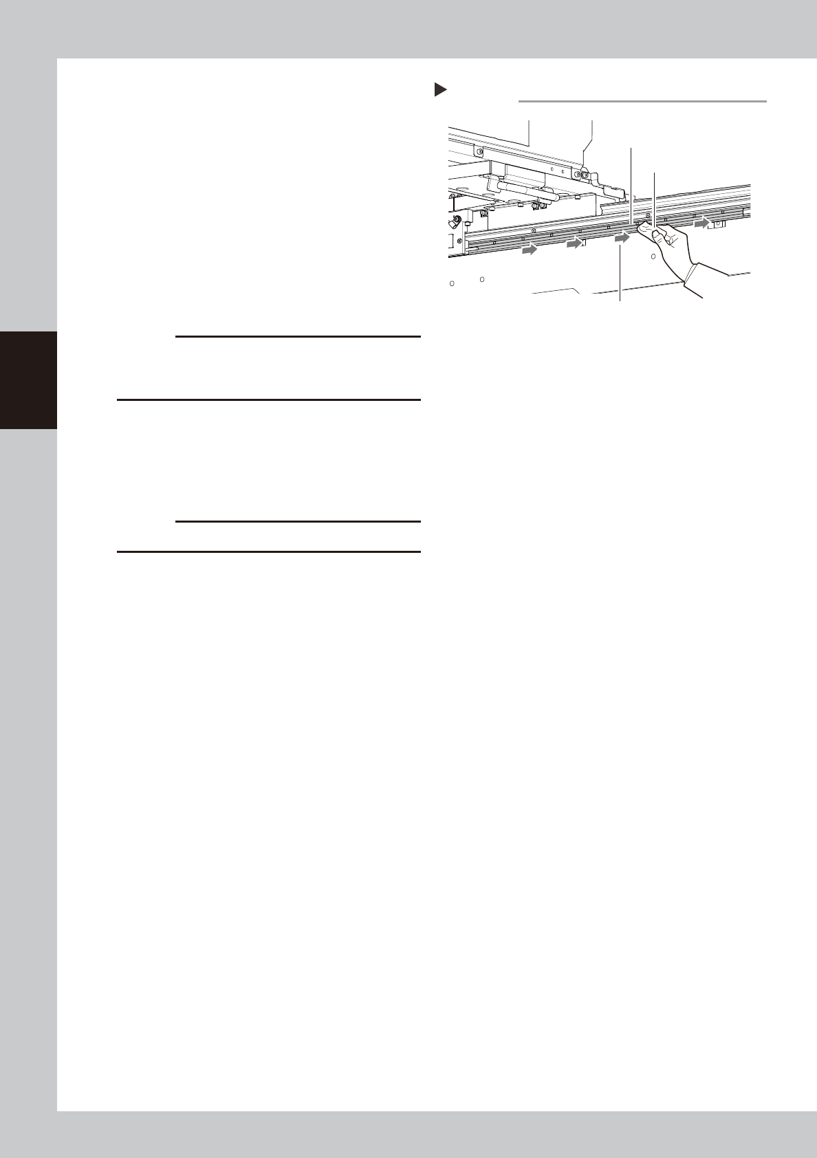
Clean the linear scale.
Use dry and lint-free cloth to dry-wipe the
linear scale. If significant soiling exists, apply
ethanol to cloth slightly and wipe it in one
direction. Then dry-wipe the area.
c
CAUTION
Do not dry-wipe the linear scale strongly.
Cleaning the linear scale
Step 8
Cloth
Linear scale
Wipe in one direction.
53328-KMK-00
3-19
3
Periodic maintenance items
2.3 Conveyor
2.3.1 Checking conveyor sensor condition and operation
This machine uses a transmission type fiber sensor as the conveyor sensor.
As the conveyor width changes, the distance between the light emitting and light receiving sensors also
changes. Accordingly, the light receiving status of the sensor may change.
Therefore, a conveyor sensor tuning function is provided on this machine that stores the sensor light receiving
status after the conveyor rail width has been changed and automatically rewrites the sensor threshold value.
By changing the conveyor rail width periodically, you can check that the conveyor sensors and conveyor sensor
tuning operate correctly.
Checking the conveyor sensor condition and operation
Light emitting
Light receiving
53329-KMK-00
1
Make the preparations for work.
Check that there is no board on the
conveyor and that there is no push-up pin in
the conveyor movement range.
2
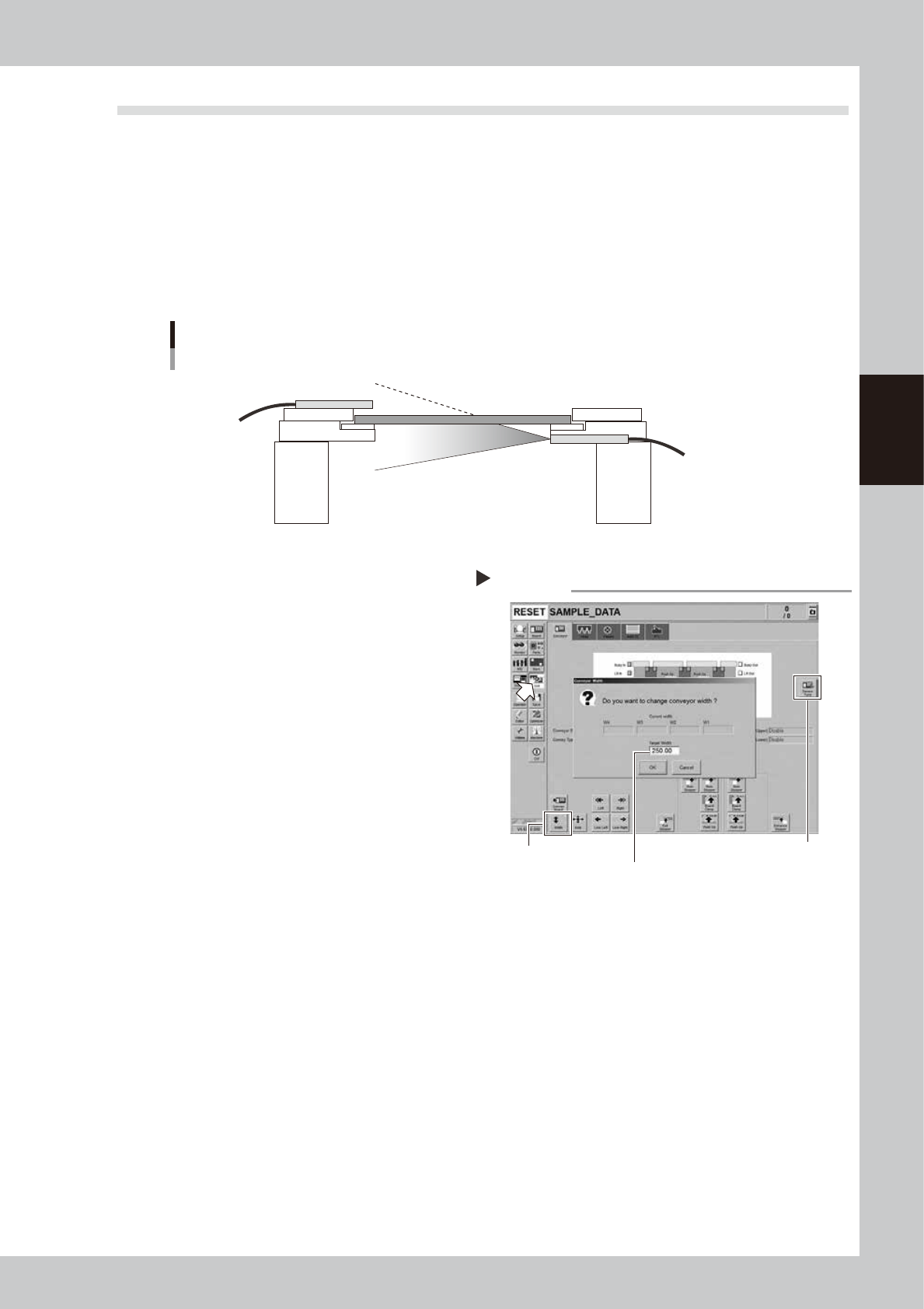
Open [Unit] - [Conveyor] screen.
3
Press the [Width] button to change
the conveyor width.
The "Conveyor Width" screen appears. Enter
a conveyor width and press the [OK] button.
The conveyor width is changed to the
specified width.
4
Check that no error occurs.
When no error message appears after the
conveyor width has been changed, the
conveyor sensors operate correctly. No
further check is needed.
If an error is displayed, perform the conveyor
tuning following the steps from 5.
5
Perform conveyor sensor tuning.
Press the [Sensor Tune] button on the right of
the [Unit] - [Conveyor] screen.
6
Check the sensor status.
Change the conveyor width again and
check that no error message appears.
7
Check the portion around the
sensor.
If the error message still appears, the light
receiving status around the sensor may be
poor, the sensor (amplifier) may malfunction,
or the fiber may break. First, remove
contaminant or dust from the sensor, change
the conveyor width again, and check that
no error message appears.
Checking the conveyor sensor
Step 2-5
[Sensor Tune] button
Enter desired conveyor width.
[Width] button
54301-KMK-00
3-20
3
Periodic maintenance items
3. 3-month maintenance
This section describes 3-month maintenance items.
3.1 Cleaning and replacing air filter
As a general guideline, the filter should be inspected once every 3 months, although this may vary depending
on the air supply conditions and the operating time. If lightly soiled, the filter can be clean by using the air
blow tool (option). The filter should be replaced when it can no longer be adequately cleaned by air-blowing.
1
Move the head unit.
1. Take off all accessories susceptible to the
magnetic fields, such as a wristwatch
and magnetic ID card.
e
2. Press the emergency stop button and
then open the machine safety cover. If
the machine is carriage type, detach
carriage to easily access to the head unit.
3. Move the head unit to a convenient
position for maintenance work.
4. Place a square cloth under head unit.
2
Detach the baffle plate.
Use a Phillips screwdriver to detach the
baffle plate shown in the figure on the right.
3
Detach the filter cap.
Turning the filter cap counterclockwise will
remove it together with the filter.
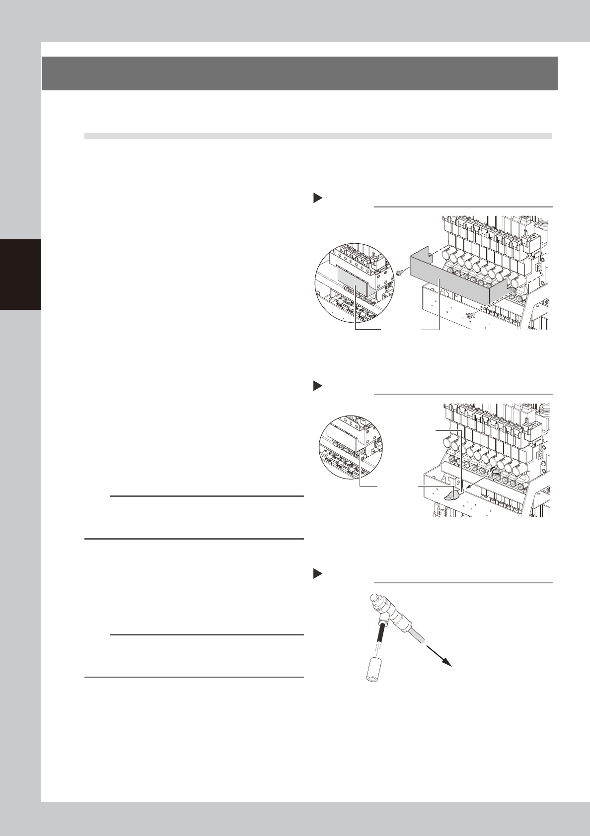
4
Clean the filter.
If the filter is only lightly soiled, it can be
cleaned with the air blow tool, and then
reused.
n
NOTE
If there are heavy dust deposits in the filter or the filter
has discolored, replace it with a new filter (KLW-M8527-
00X).
5
Attach the filter cap.
1. Fit the filter into the filter cap.
2. Insert the filter cap into its original
position and turn it clockwise to secure it.
3. Remove the square cloth.
n
NOTE
When attaching the filter, check also the status of the
gasket (KLW-M715B-00X). If the gasket deteriorates or is
deformed, replace it with a new one.
6
Attach the baffle plate.
1. Attach the baffle plate to the original
position with Phillips screwdriver.
2. Remove the square cloth.
Detaching the baffle plate
Step 2
Baffle plate
FM head
HM head
53330-KMK-00
Detaching the filter cap
Step 3
Filter cap
Filter
FM head
HM head
53331-KMK-00
Cleaning the filter
Step 4
Filter
Air blow tool
To air connector
53332-KMK-00