YSM20R_YSM20WR_Mainte_E.pdf - 第183页
Appendix Appendix Contents 1. Specifications A-1 1.1 Air regulator unit A-1 1.2 Power connection terminals A-2 1.3 Connection between machines A-3 1.3.1 PREVIOUS INTERF ACE connector A-3 1.3.2 NEXT INTERF ACE connector A…
6-26
6
How to replace consumable parts
4
Check the valve operation.
1. Turn on the supply air and power on the
machine.
2. When replaced carriage clamp/unclamp
valve, clamp and unclamp the carriage
to check that carriage can be set
correctly.
TIP
The carriage clamp valve operation can be also
checked on [Unit] - [I/O] screen. See the figure below.
3. When replaced valve for raising multi-
camera side light, check the operation
on [Unit] - [I/O] screen.
n
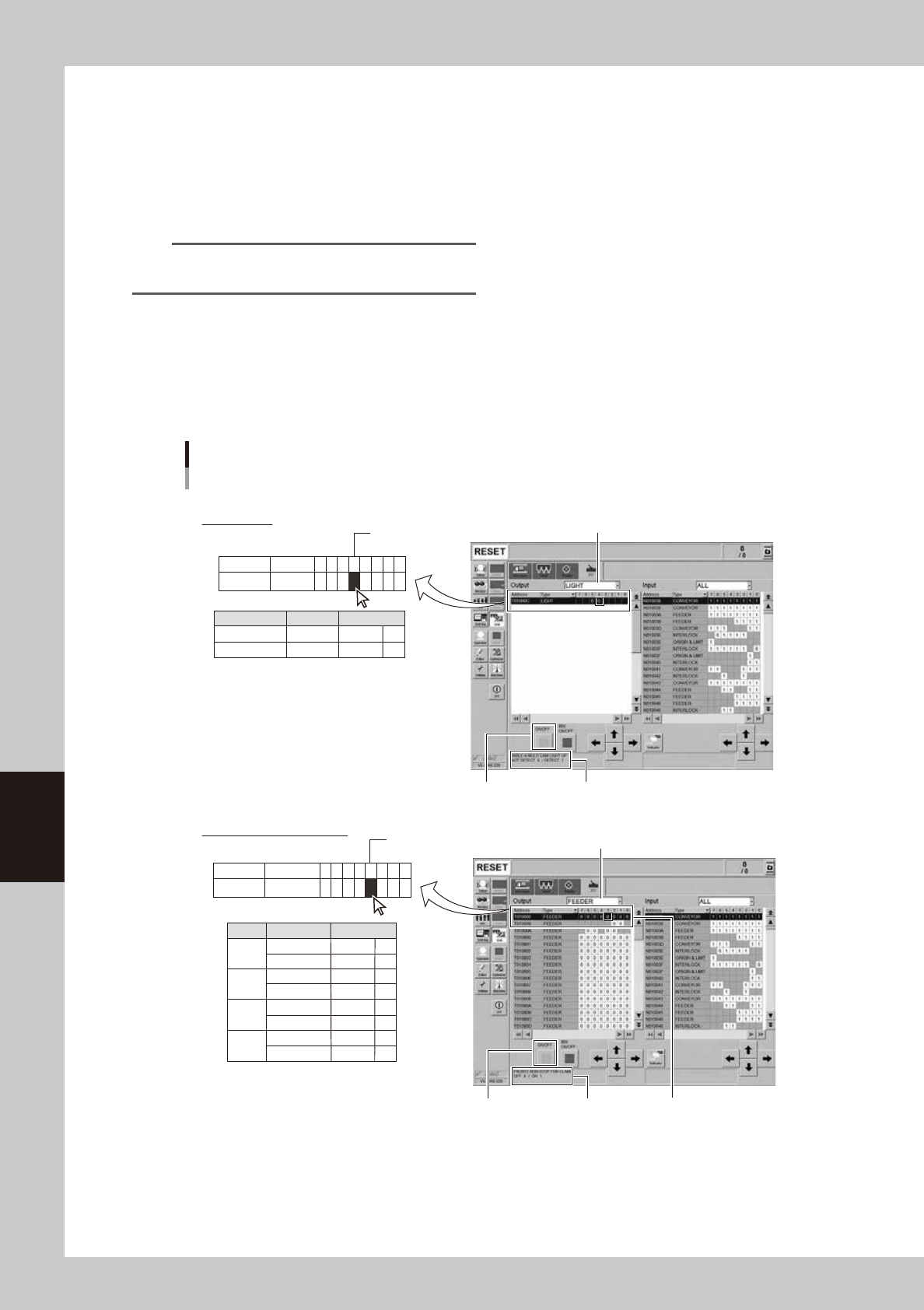
Checking valve operation on "I/O" screen
Check the valve operation as below after replacing it.
Checking valve operation
5
7
6
Example: T010000-3
Address
T010000
Type
FEEDER
7 6 5 4 3 2 1 0
0
00 0 0 000
Example: T01000C-4
Address
T01000C
Type
LIGHT
7 6 5 4 3 2 1 0
00
Carriage
2
1
0
4
3
Address
T010000
T010000
T010000
T010000
T010000
T010000
T010000
T010000
F1
F2
R1
R2
UNCLAMP
CLAMP
UNCLAMP
CLAMP
UNCLAMP
CLAMP
UNCLAMP
CLAMP
Description
[Unit] - [I/O] screen
Select “FEEDER” from “Output”.
Multi-camera
5
4
Address
T01000C
T01000C
UP
UP
TABLE-A (Front)
TABLE-B (Rear)
Description
Carriage clamp (reference)
Multi-camera
Select address.
[ON/OFF] button Address description
Select “LIGHT” from “Output”.
[ON/OFF] button Address description
54605-KMK-00

Appendix
Appendix
Contents
1. Specifications A-1
1.1 Air regulator unit A-1
1.2 Power connection terminals A-2
1.3 Connection between machines A-3
1.3.1 PREVIOUS INTERFACE connector A-3
1.3.2 NEXT INTERFACE connector A-4
2. Maintenance parts A-5
2.1 YSM20R/YSM20WR consumable parts list A-5
2.2 YSM20R main unit maintenance parts list A-6
2.3 YSM20WR main unit maintenance parts list A-14
2.4 Tray component supply unit maintenance parts list A-21
A-1
Appendix
1. Specifications
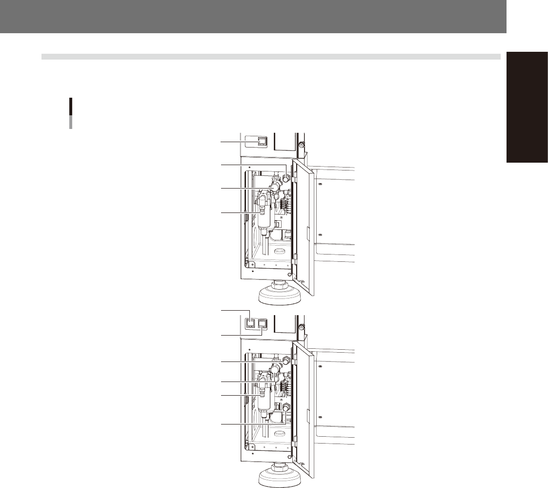
1.1 Air regulator unit
The regulator that regulates the air pressure supplied to the air drive section of this machine is located behind
the front lower left panel of the main unit. Specify the appropriate air pressure setting shown below.
Air pressure regulator and pressure gauge
For 1-beam
For 2-beam
Air supply/exhaust switch
Source air connector
Air pressure regulator
Digital pressure gauge
Digital pressure gauge
(A-table)
Digital pressure gauge
(B-table)
Air supply/exhaust switch
Source air connector
Air pressure regulator
(A-table)
Air pressure regulator
(B-table)
53A01-KMK-00
n
Supply air pressure
This is the pressure of the source air supplied to the machine. Before setting the air pressure with the air regulator, make
sure that this supply air pressure is in the following optimal range.
YSM20R/YSM20WR: 0.45MPa to 0.70MPa
n
Digital pressure gauge
When within the normal range, the air pressure displays in green. When the air pressure is beyond the upper/lower limit
values (air down detection), an error occurs, and the air pressure displays in red.
n
Set pressure and air-down detection pressure
Air pressure setting for machine : 0.40MPa (±0.01)
(When the air pressure reaches 0.45MPa, the air pressure display turns red.)
Pressure-drop detection level : 0.33MPa
n
Air supply/exhaust switch (valve)
Turning this switch to the right shuts off air supply and exhausts air that remains inside the machine.
n
Source air connector
Prepare an air hose with an inner diameter of at least 8 mm having a 40SH socket (Nitto Koki, or equivalent), and
connect it to this connector. Use dry, clean air passed through an air filter.