YSM20R_YSM20WR_Mainte_E.pdf - 第98页
3-37 3 Periodic maintenance items 4.1.4 FM head: Simple cleaning of side-view camera T he light diffuser plate and mirror of the side-view camera are attached to the head. The light diffuser plate or mirror opening of th…
3-36
3
Periodic maintenance items
4.1.3 HM head: Cleaning scan camera
The light diffuser plate and prism for the scan camera are attached to the opening at the left end of the camera.
These diffuser plate and prism may become dirty due to dust and dirt. Periodic cleaning is recommended.
c
CAUTION
Do not apply strong force to the camera parts during cleaning. Doing so may damage the glass components used in
the camera unit.
1
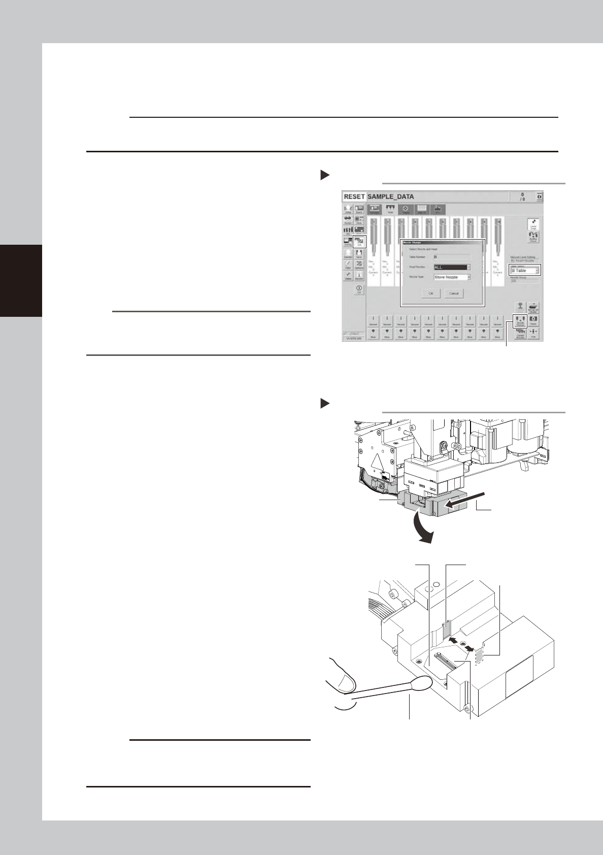
Store all nozzles to nozzle station.
1. Open the [Unit] - [Head] screen.
2. Select desired head unit from "Table
Select".
3. Press the [Nozzle Change] button.
4. Select "ALL" for "Head Number" and
select "Store Nozzle" for "Nozzle Type" on
the "Nozzle Change" screen.
5. Press the [OK] button to return all nozzles
to the nozzle station.
n
NOTE
If the machine is not equipped with a nozzle station,
press the emergency stop button and then remove the
nozzles manually.
e
2
Move the head unit.
1. Press the emergency stop button and
then open the machine safety cover.
2. If the machine is carriage type, detach
carriage to easily access to the head unit.
3. Move the head unit to a convenient
position for maintenance work.
3
Move the scan camera.
1. Check that all heads locate upper ends.
If they locate the position of hitting scan
camera, move all heads (nozzle holder
sections) manually to the upper ends.
2. Move the scan camera to left end (No.
10 head side). At this time, do not apply
any excessive force.
4
Wipe the diffuser plate and prism.
1. Use a cotton swab to remove dust and
dirt on the upper surface of the main
light diffuser plate and on the prism
surface. Since the prism surface is
narrow, twist the end of the cotton swab
into a pointed tip and use it to wipe the
prism surface lightly.
2. Wipe the side-view light diffuser plate
and prism using a cotton swab. Use a
hand mirror when wiping the prism
surface since it cannot be seen from the
front.
c
CAUTION
Do not use solvent. Solvent may cause the surface finish
of the prism to peel or flake and the diffuser plate to
discolor.
Storing nozzles
Step 1
[Nozzle Change] button
54303-KMK-00
Cleaning light diffuser plate and prism
Step 3, 4
Cotton swab
Main diffuser plate
Side-view diffuser plate
Side-view prism
Main prism
Move manually.
Scan camera
53351-KMK-00
3-37
3
Periodic maintenance items
4.1.4 FM head: Simple cleaning of side-view camera
The light diffuser plate and mirror of the side-view camera are attached to the head. The light diffuser plate or
mirror opening of the side-view camera may be contaminated by dust. The periodic cleaning is recommended.
c
CAUTION
Do not apply strong force to the camera parts during cleaning. Doing so may damage the glass components used in
the camera unit.
e
1
Move the head unit.
1. Press the emergency stop button and
then open the machine safety cover.
2. If the machine is carriage type, detach
carriage to easily access to the head unit.
3. Move the head unit to a convenient
position for maintenance work.
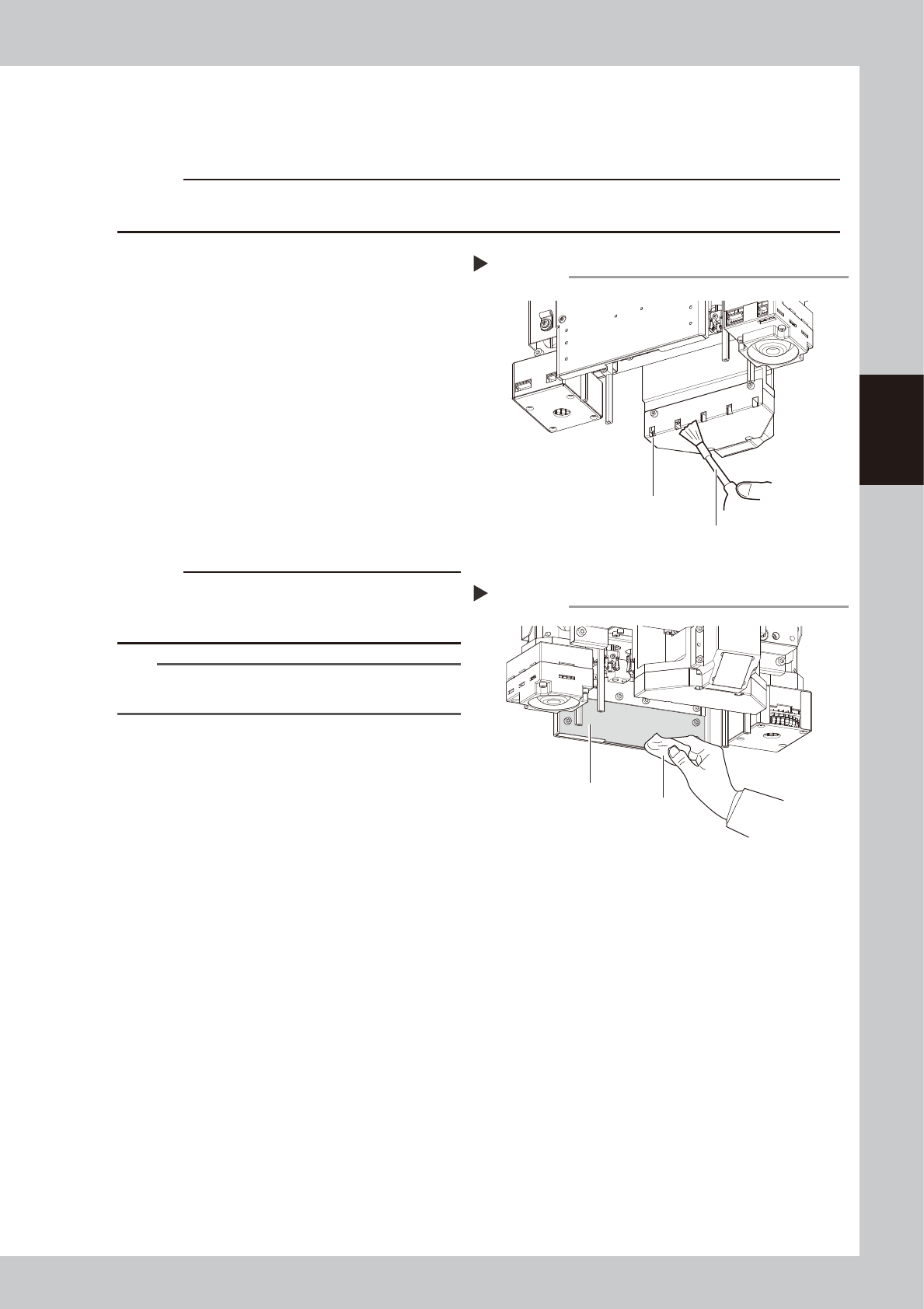
2
Clean the opening.
Use an blower brush to remove the dust from
the opening.
3
Clean the diffuser plate.
Apply a small amount of lens cleaner to
lint-free cloth or cleaning paper and clean
the diffuser plate.
c
CAUTION
Do not use solvent. If solvent is used, this may cause the
surface treatment of the diffuser plate to be peeled off
or discolored.
TIP
The blower brush , lens cleaner, and cleaning paper are
optional purchase items.
Cleaning the opening
Step 2
opening
Blower brush
53352-KMK-00
Cleaning the diffuser plate
Step 3
Diffuser plate
Cloth
53353-KMK-00
3-38
3
Periodic maintenance items
4.2 Base unit
4.2.1 Cleaning fan filter for control box
The air intake fan and the filter are in the control box controlling the machine. The filter should be cleaned
once 6-month, although this may vary depending on the machine condition.
n
Machine cover types
The machine cover varies depending on the machine types such as feeder exchange carriage or fixing bank. This manual
describes the procedure of the machine equipped with a carriage and a tape cutter. The procedure of detaching the cover
on the front right only is provided this time. However if cATS10 or sATS30 is not installed on the front side of the
machine, it is easier to work by detaching the cover on the front left as well.
1
Power off the machine.
1. If the machine is carriage type, detach
the front carriage.
2. Exit the software and power off the
machine.
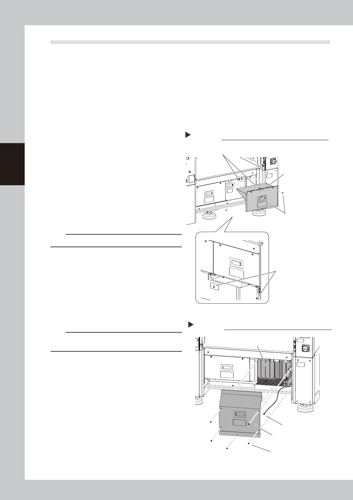
2
Detach the tape cutter safety cover.
1. Remove the mounting screws of the tape
cutter safety cover (front right) with a
Phillips screwdriver.
2. Pull the tape cutter cover forward and
detach it.
n
NOTE
The interlock key is attached on the tape cutter cover.
3
Detach the inner cover
1. Remove the mounting screws of the inner
cover (front right) with a Phillips
screwdriver.
2. Detach the cover.
3. A ground wire is connected to the rear
side of the cover. Remove the screw
mounting the ground wire with a Phillips
screwdriver.
n
NOTE
Toothed washer is installed to the ground wire mounting
screw. Make sure not to lose it when removing screws.
4
Clean around the control box.
If dust is around the control box, clean the
area with a vacuum cleaner, etc. before
detaching the filter.
Detaching the tape cutter safety cover
Step 2
Tape cutter safety cover
(front right)
Bottom of cover
Remove 2 screws
at the bottom of cover.
Cover mounting screw
Interlock key
53380-KMK-00
Detaching the cover
Step 3
Cover (front right)
Cover mounting screw
Control box
Ground wire
mounting screw
53381-KMK-00