YSM20R_YSM20WR_Mainte_E.pdf - 第129页
3-68 3 Periodic maintenance items 5.6 Recognition equipment 5.6.1 FM Head: Cleaning inside of side-view camera T he simple cleaning of the side-view camera described in "4.1.4 FM head: Simple cleaning of side-view c…
3-67
3
Periodic maintenance items
4
Check media status.
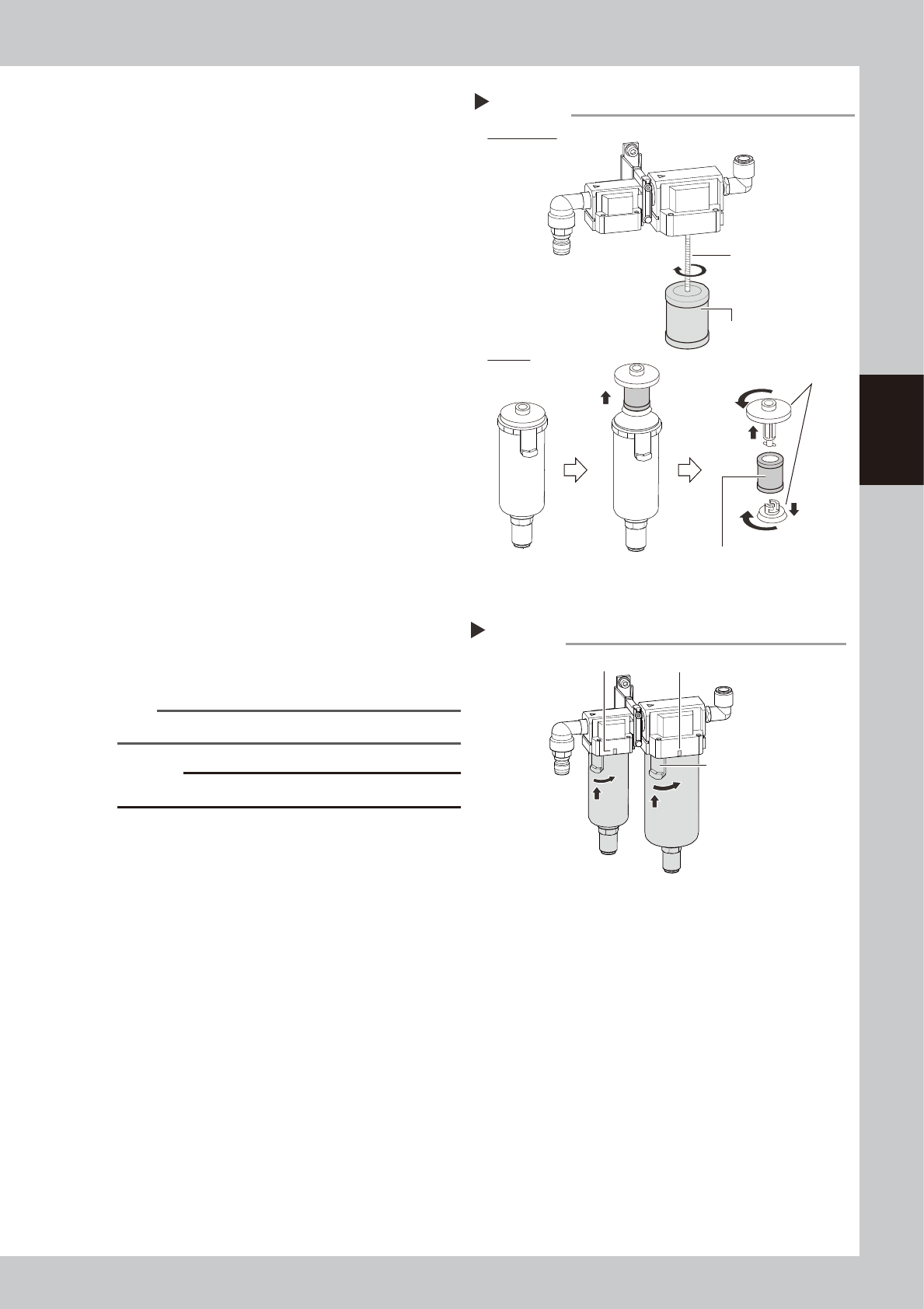
Oil mist filter:
The mist filter element is attached with the
screw of main unit. Rotate the oil mist filter
to detach it.
Air filter:
The filter element is attached between the
adopters on top and bottom of filter
element. Pull up the filter element with
adopters. Turn the adopters to detach filter
element.
Check that no dirt or clogging is in the
media. If the media is dirty, replace it with
new one on the consumable parts list.
5
Clean the inside of the filter cup.
1. Lightly clean the filter cup with water.
2. Pour water-diluted neutral detergent into
the filter cup and clean the inside while
shaking it.
3. Air blow the filter cup and wipe away
any moisture with cloth.
6
Attach filter element and cup.
1. Attach the filter element in reverse order
of detaching.
2. Aligning the button with the position
where the cup was pulled (45
°
to the
left), push up the cup.
3. Turn the cup to the mark on the filter
housing clockwise.
n
NOTE
The cup clicks when turning it to the mark.
c
CAUTION
Make sure not to lose the O-ring for cup when attaching.
7
Connect the air coupler.
1. Connect the air coupler and check that
air is not leaking.
2. Turn the “Air supply/exhaust” switch
(valve) counterclockwise (Sup) to supply
air again.
Mist filter element
Detaching media and checking condition
Step 4
Filter element
Attach with screw.
Oil mist filter
Air filter
Adopters
53384-KMK-00
Attaching cup
Step 6
Mark
Mark
Button
53385-KMK-00
3-68
3
Periodic maintenance items
5.6 Recognition equipment
5.6.1 FM Head: Cleaning inside of side-view camera
The simple cleaning of the side-view camera described in "4.1.4 FM head: Simple cleaning of side-view
camera" in this chapter is performed. However, if the recognition error related to the side-view camera occurs
frequently, it is recommended to clean the inside of the reflector plate.
c
CAUTION
Do not apply strong force or shock to the camera unit and lighting unit during cleaning. Optical axis adjustment might
become unreliable.
c
CAUTION
When a trouble related to lighting, etc. occurred, contact YAMAHA sales representatives. The disassembly and
cleaning of the machine made by the customer is beyond the coverage of the warrantee.
1
Power off the machine.
1. If the machine is carriage type, detach
carriage to access to the head unit.
2. Exit the software.
3. Power off the machine.
2
Move the head unit forward.
1 Open the machine safety cover.
2. Move the head unit forward.
3. Place a square cloth under the head
unit.
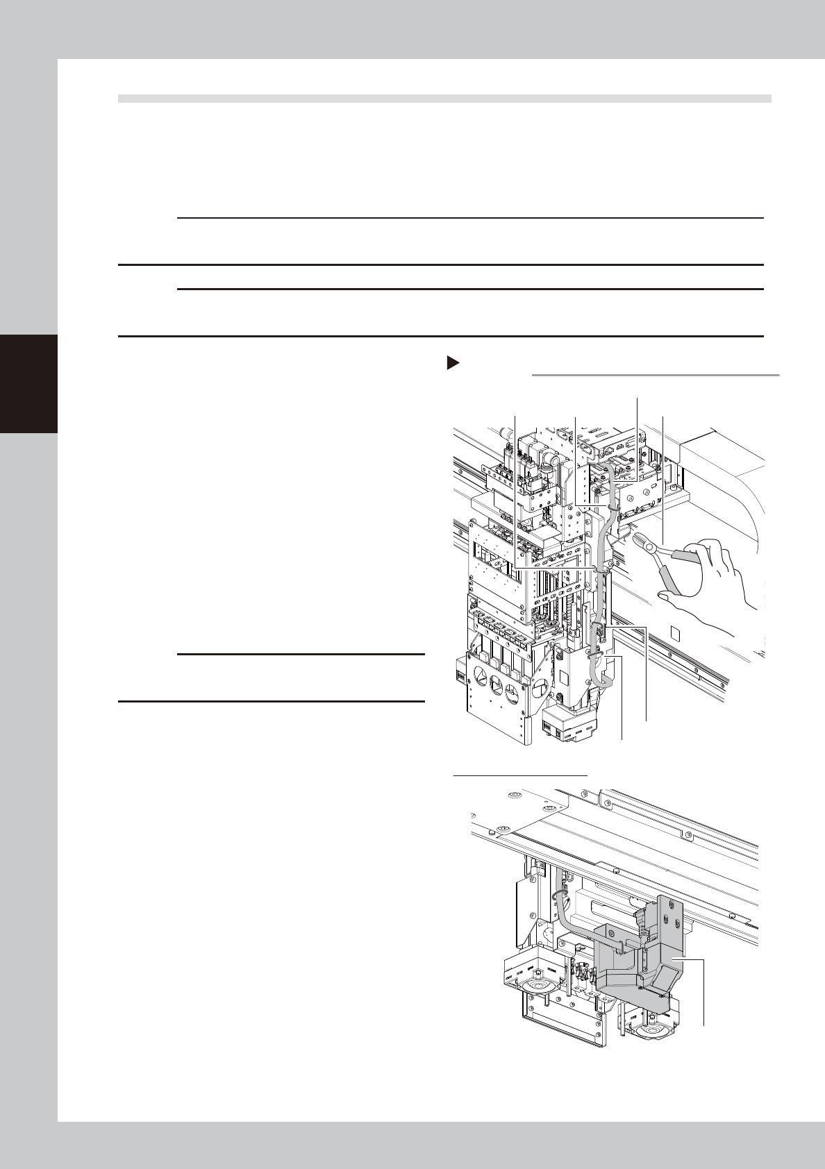
3
Cut cable ties fixing side-view
camera cable.
Cut 4 cable ties fixing side-view camera
cable with cutting pliers.
c
CAUTION
Make sure not to damage the cable when cutting
cable ties.
Cutting cable ties
Step 3
Cable tie 1 Cutting pliersCable tie 2
Cable tie 3
Cable tie 4
Lower side of FM head unit
Side-view camera cable
Side-view camera
assembly
53386-KMK-00
3-69
3
Periodic maintenance items
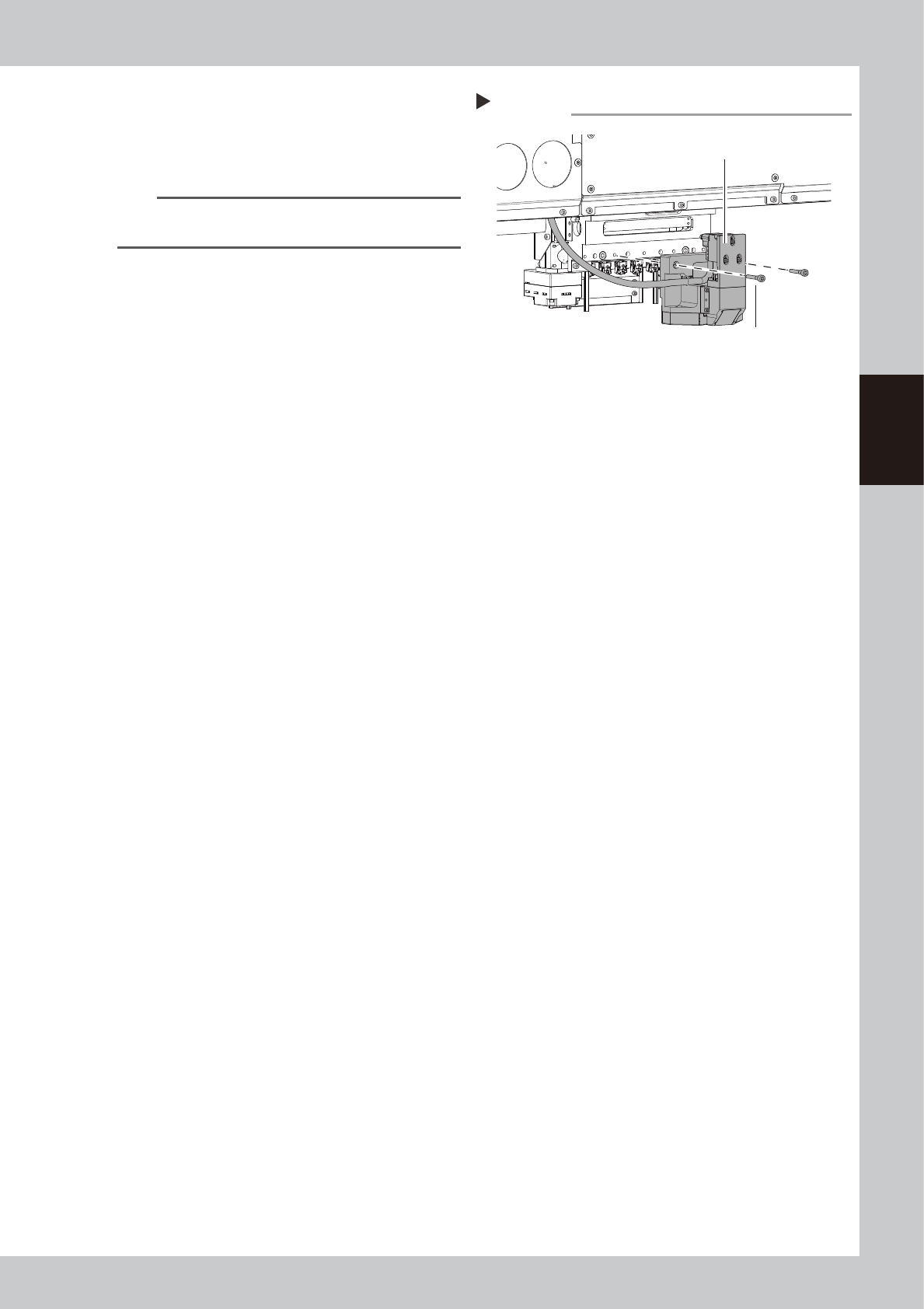
4
Detach side-view camera assembly.
1. Remove 2 mounting bolts of side-view
camera assembly with hex wrench (4).
2. Detach side-view camera assembly.
n
NOTE
The knock pin is installed to the side-view camera
assembly for positioning.
Detaching side-view camera assembly
Step 4
Side-view camera assembly
Mounting bolt
53387-KMK-00