YSM20R_YSM20WR_Mainte_E.pdf - 第76页
3-15 3 Periodic maintenance items 4 Apply grease. 1. As shown in the figure on the right, move the head unit to one side manually so that the grease nipple can be seen. 2. The grease nipple at the center of those aligned…
3-14
3
Periodic maintenance items
2.1 X-axis
This section explains the X-axis inspection, cleaning, and lubrication procedures. For details regarding
lubrication points and the lubrication types, see "Chapter 5 Lubrication points". The user must provide the
grease gun (standard nozzle and bent type nozzle) and the prescribed grease (NSL).
2.1.1 Cleaning and greasing X-axis ball screw
1
Prepare for work.
e
1. Take off all accessories susceptible to the
magnetic fields, such as a wristwatch
and/or magnetic ID card.
2. Press the emergency stop button and
then open the machine safety cover.
3. Detach the carriage if the machine is the
carriage type.
4. Place a square cloth on the Y-axis linear
area and the push-up plate.
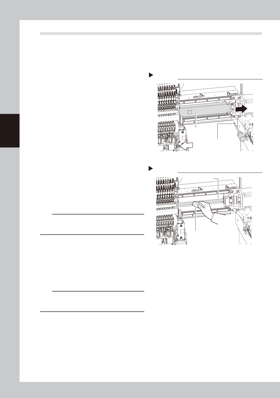
2
Remove the grease spattering
prevention cover.
Remove the X-axis grease spatter prevention
cover.
1. Use a Phillips screwdriver to remove the
screws that secure the grease spattering
prevention cover (right side when viewed
from the head).
Loosen the screws on the left side lightly.
2. Move the head to the left and pull out
the grease spattering prevention cover
toward the right to remove it.
TIP
Reattach the X-axis grease spatter prevention cover by
reversing the above removal procedure. Attach by
pressing the end of the cover which is at motor side.
3
Clean the ball screws.
1. Grasp the handle and move the head
unit to one end.
2. Wipe away the old grease and dirt from
the ball screw with a lint-free cloth.
3. Move the head unit to the opposite end,
then wipe the opposite-side ball screw.
n
NOTE
When cleaning the ball screw, carefully clean its
groove area as well. Be sure that the cloth, etc., being
used to clean the ball screw does not produce lint, etc.
Removing the spatter prevention cover
Step 2
Grease spattering
prevention cover
Cover securing screws
53320-KMK-00
Cleaning the ball screw
Step 3
Cloth
Ball screw
53321-KMK-00
3-15
3
Periodic maintenance items
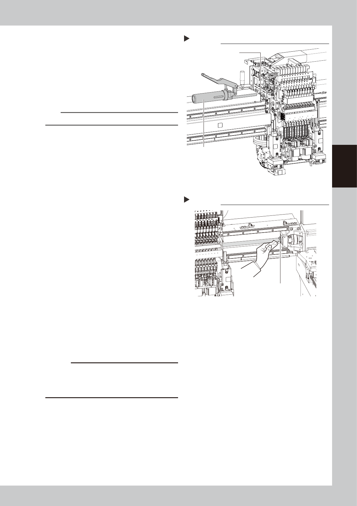
4
Apply grease.
1. As shown in the figure on the right, move
the head unit to one side manually so
that the grease nipple can be seen.
2. The grease nipple at the center of those
aligned at 3 locations is the ball screw
nipple. Use a grease gun (standard type)
to inject the prescribed grease at the
grease nipple.
n
NOTE
Inject until the grease begins to seep out from the gap.
5
Wipe off the excess grease.
1. Grasp the handle and move the head
unit to one end.
2. Wipe all excess grease from the ball
screw and nut end faces.
3. Move the head unit to the opposite end
and wipe all excess grease from the
opposite-end ball screw and nut end
faces.
6
Perform a warm-up.
1. Remove the square cloth.
2. Reattach the spatter prevention cover.
3. Close the machine safety cover and
cancel the emergency stop. Attach the
carriage if the machine is the carriage
type.
4. Open the "Warm-up" screen and perform
the warm-up operation for approximately
8 minutes.
e
7
Check the grease condition.
1. After stopping warming up, press the
emergency stop button and then open
the machine safety cover.
2. Remove the anti grease splatter cover.
3. Wipe the grease accumulated on the
ball screw and ball screw end surface.
4. Attach the anti grease splatter cover.
c
CAUTION
Repeat Steps 6 and 7 until grease accumulations no
longer occur. Beginning production with grease
accumulations present could cause the grease to
splatter.
Applying grease
Step 4
Grease nipple (center)
Grease gun (standard type)
53322-KMK-00
Wiping off the excess grease
Step 5
Excess grease
53323-KMK-00
3-16
3
Periodic maintenance items
2.1.2 Cleaning and lubricating X-axis guide
1
Prepare for work.
1. Take off all accessories susceptible to the
magnetic fields, such as a wristwatch
and/or magnetic ID card.
e
2. Press the emergency stop button and
then open the machine safety cover.
3. Detach the carriage if the machine is the
carriage type.
4. Place a square cloth on the Y-axis linear
area and the push-up plate.
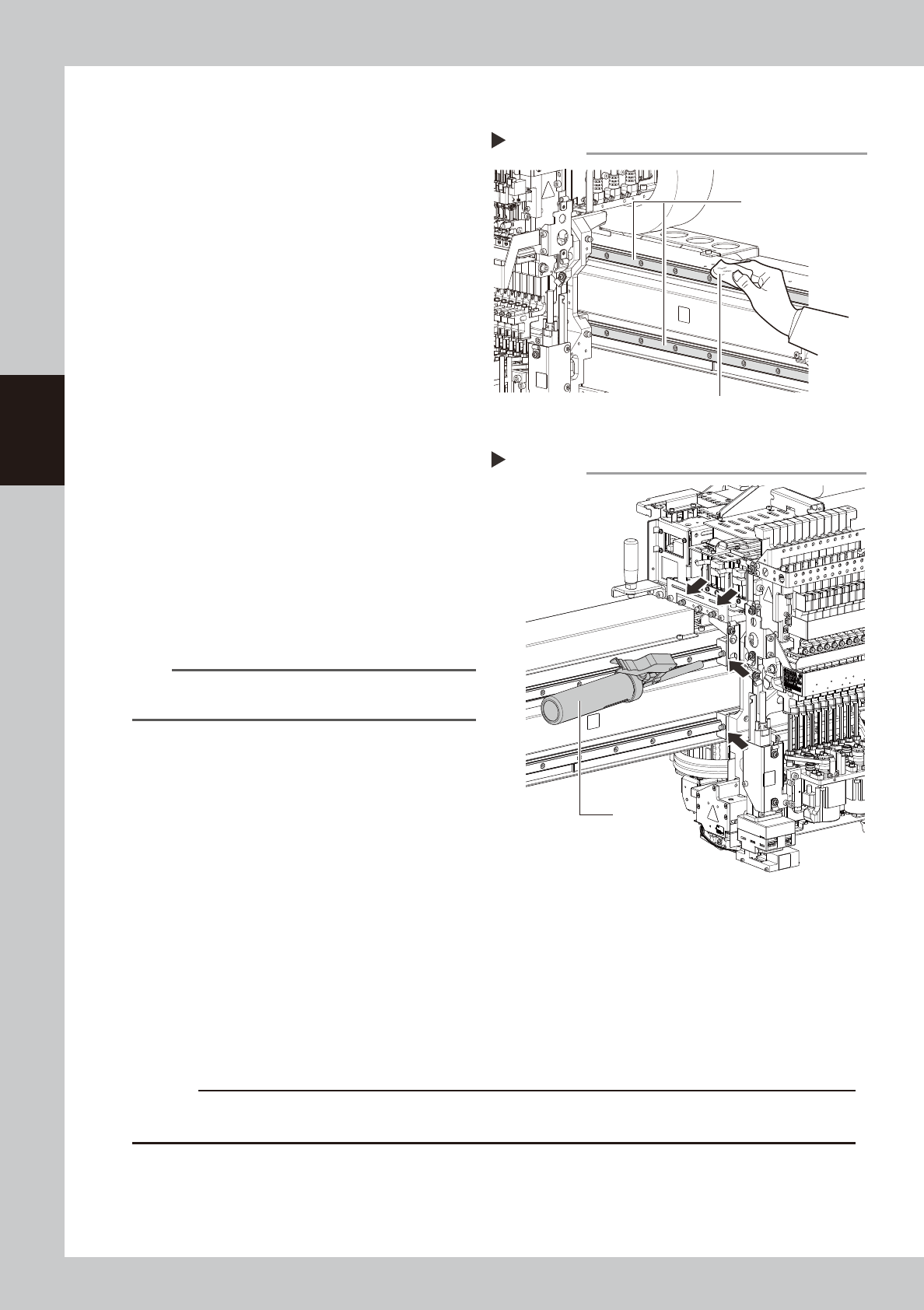
2
Clean the guide.
1. Grasp the movement handle and move
the head unit to one end.
2. Using lint-free cloth, wipe the old grease
and soiling on the entire guide.
3. Move the head unit to the opposite side,
then clean the opposite-side guide.
3
Inject the grease.
Using a grease gun (standard type), inject
the prescribed grease (NSL) at the X-axis
guide's grease nipples (4 nipples).
4
Spread the grease.
Move the head unit left and right several
times manually to spread the grease.
n
NOTE
The grease you have injected through the nipple oozes
to the guide when moving the axis.
5
Wipe off the excess grease.
Wipe off the excess grease from both ends
of the guide.
6
Apply the grease again.
Repeat Steps 3 to 5 twice again.
After that, visually check that the grease is
applied to the entire guide.
7
Perform a warm-up.
1. Remove the square cloth.
2. Close the machine safety cover and cancel the emergency stop. Attach carriage if the machine is
the carriage type,
e
3. Open the "Warm-up" screen and perform the warm-up operation for approximately 8 minutes.
4. After stopping warming up, press the emergency stop button and then open the machine safety
cover.
5. Wipe the grease accumulated on the guide end surface.
c
CAUTION
Repeat Step 7 until grease accumulations no longer occur. Beginning production with grease accumulations present
could cause the grease to spatter.
Cleaning the guide
Step 2
Cloth
Guide
53324-KMK-00
Injecting the grease
Step 3
Grease gun
(standard type)
53325-KMK-00