YSM20R_YSM20WR_Mainte_E.pdf - 第140页
4-5 4 Maintenance of options 3. Nozzle station 3.1 Checking and cleaning nozzle sensor (1 year) When the machine is equipped with the nozzle station (option), it is necessary to periodically c heck the nozzle detection s…
4-4
4
Maintenance of options
2. UPS (Uninterruptible Power Supply)
2.1 Replacing the UPS battery (3-year)
The battery is a consumable item. Even though the service life of the UPS may vary depending on the operating
environment, such as ambient temperature, it is recommended to replace the battery with a new one (KGA-
M6566-30X) at reference intervals of 3 years. The following describes how to replace the battery that is
incorporated into the UPS.
w
WARNING
BATTERY REPLACEMENTS SHOULD BE PERFORMED ONLY BY THOSE WITH ELECTRICAL WORK EXPERIENCE.
1
Power off the machine
Power off UPS several seconds after
powering off the machine.
w
WARNING
DO NOT ATTEMPT THIS BATTERY REPLACEMENT
PROCEDURE WHILE THE MACHINE IS IN THE EMERGENCY
STOP STATUS OR THE UPS FUNCTION IS RUNNING.
2
Remove the front panel.
Use a Phillips screwdriver to remove the
screws which mount the front panel, then
remove the front panel.
3
Disconnect the battery connector.
Disconnect the UPS side and internal battery
side connectors.
4
Remove the battery mounting
fixture.
Remove the battery fixture mounting screws,
then remove the battery mounting fixture.
5
Replace the removed battery with a
new one.
Extract the old battery and insert a new
battery in its place.
6
Reinstall the battery.
Reverse Steps 2 to 4 above to reinstall the
battery.
7
Check the UPS status.
1. Turn the machine power ON.
2. Press the ON button on the UPS operation
panel to check that the BATTERY LED is
OFF.
8
Write the battery replacement
year/month.
Write the battery replacement year/month
on the UPS WARNING label (see "Safety
instructions" in this manual).
n
NOTE
See the manufacturer's instructions for detailed
operation of the UPS.
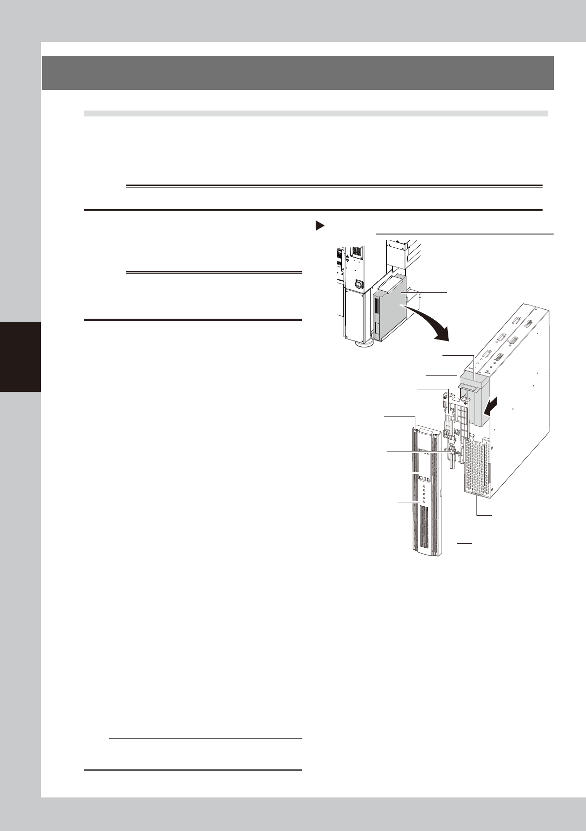
Replacing UPS internal battery
UPS unit
Lower right portion on
front of machine
Internal battery
Internal battery
side connector
UPS side battery
connector
Battery mounting fixture
Front panel
Front panel hook
Battery mounting fixture
mounting screw
Front panel
mounting screws
UPS operation panel
Step 2-6
53404-KMK-00
4-5
4
Maintenance of options
3. Nozzle station
3.1 Checking and cleaning nozzle sensor (1 year)
When the machine is equipped with the nozzle station (option), it is necessary to periodically check the nozzle
detection sensor status.
c
CAUTION
If the nozzle station sensor cannot detect the nozzle correctly, the nozzle change does not operate correctly or the
production cannot continue due to nozzle detection error.
e
1
Make the preparations for work.
1. Return all nozzles to the nozzle station.
2. Press the emergency stop button and
then open the machine safety cover.
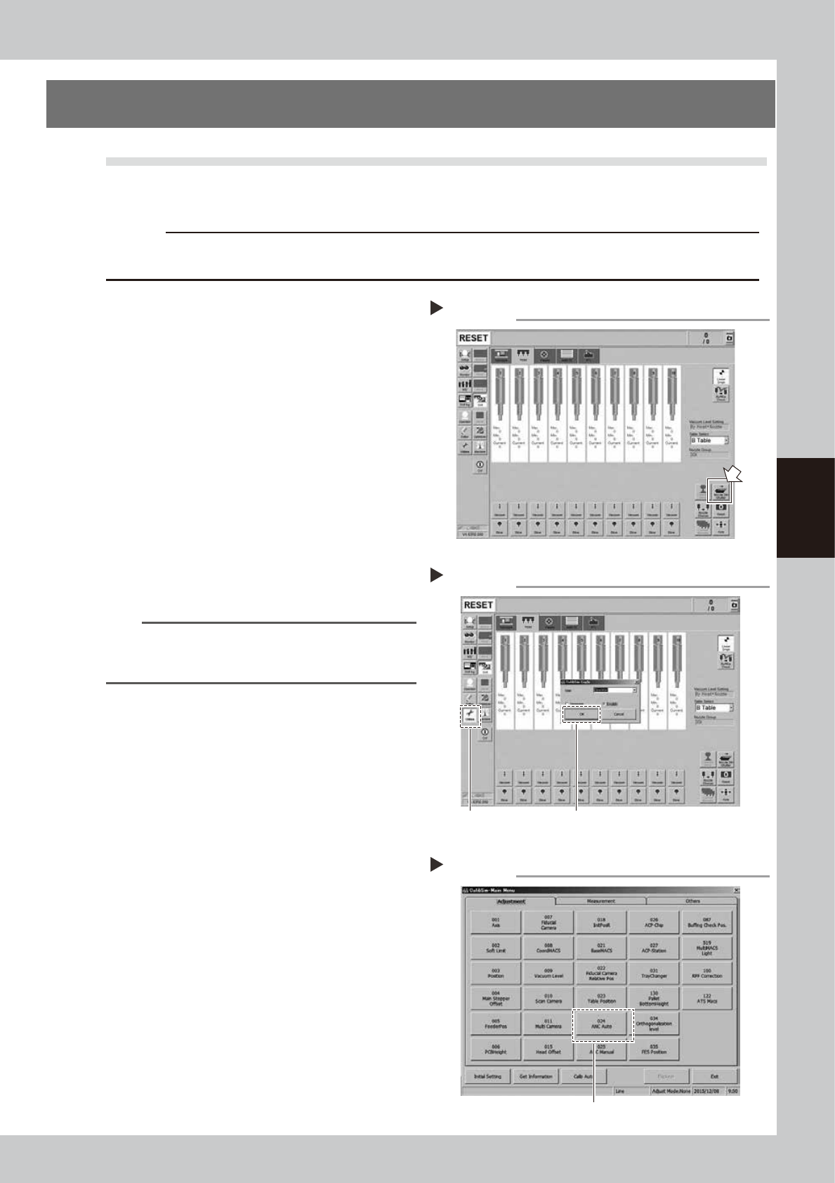
2
Open the shutter of the nozzle
station (hereafter "ANC").
1. Open the [Unit] - [Head] screen.
2. Press the [Nozzle. Stn Shutter] button to
open the ANC shutter.
3
Open the Utilities mode.
1. Press the [Utilities] button on the left of
the screen.
2. The "Login" window will appear. Check
that "Operator" is shown in the “User”
field, and then press the [OK] button.
n
NOTE
When logging-in to the Utilities mode with "User:
Operator", the machine set values cannot be changed
or saved.
4
Select [ANC Auto].
Press the [024 ANC Auto] button.
Opening the nozzle station shutter
Step 2
54400-KMK-00
Opening the Utilities mode
Step 3
Select [Utilities].
Select [OK] with "User: Operator".
54401-KMK-00
Selecting [ANC Auto]
Step 4
Select [024 ANC Auto].
54402-KMK-00
4-6
4
Maintenance of options
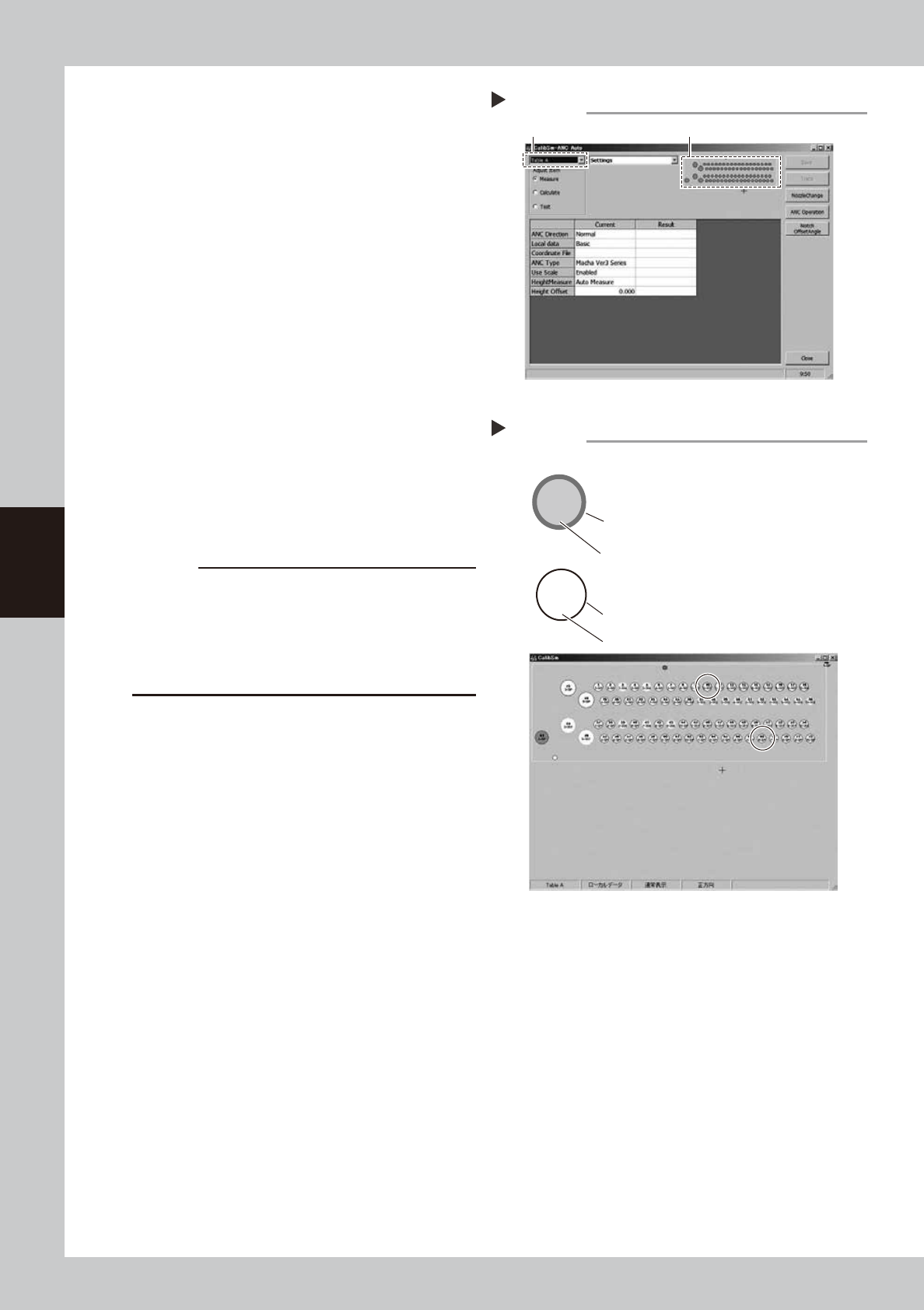
5
Open the ANC Auto screen.
Press the [024 ANC Auto] button.
1. Select a desired table from the pull-down
menu at the upper left portion of the
screen.
2. Click the ANC figure on the right.
6
Check the ANC sensor operation.
1. Check that the nozzle storage status
shown on the screen is the same as the
actual nozzle storage status referring to
the nozzle storage position/sensor status
in the figure.
2. Remove the nozzle manually and check
that no nozzle is displayed at the target
storage position.
7
Clean the ANC.
If the nozzle detection status is different from
the actual nozzle presence status, remove
the nozzle and visually check the inside. If
any dust or chip is found, remove it and
clean the inside of the nozzle using the
vacuum assembly.
c
CAUTION
If the nozzle detection status inside the ANC does not
become stable for a reason other than clear reason,
such as dust, etc., or if the nozzle cannot be detected,
contact your distributor. The disassembly and cleaning
performed by the customer are not covered by the
warranty.
8
Close the ANC shutter.
Press the [Nozzle. Stn Shutter] button to close
the ANC shutter.
Opening the ANC Auto screen
Step 5
Select the table A or table B. Click the ANC figure.
54403-KMK-00
2-303
10
7-SP
68
Checking the ANC sensor operation
Step 6
303 nozzle to be used for head 2
Storage position: No. 10
Colored frame (red/blue/yellow/green, etc.):
Nozzle is already registered.
Special nozzle to be used for head 7
Storage position: No. 68
Black frame: Nozzle is not registered.
Gray out: Nozzle is present currently.
White: Nozzle is not present currently.
Example of nozzle storage position/sensor status
54404-KMK-00