YSM20R_YSM20WR_Mainte_E.pdf - 第138页
4-3 4 Maintenance of options 1.2 Replacing the ionizer discharge needle (2-year) Replace ionizer discharge needle (KJX-M83P1-00X : NEEDLE SP ARE SET/5 pcs) once every 2 y ears or if an error still occurs even after perfo…
4-2
4
Maintenance of options
1.1 Cleaning the ionizer discharge needle (Monthly)
Perform this work monthly or if the LED on the ionizer main unit is lit red.
1
Power off the ionizer.
1.
Press the emergency stop button and
then open the machine safety cover to
stop the power supply to the ionizer.
2.
Check that the green LED of the "POWER"
on the ionizer is turned off.
w
WARNING
A VOLTAGE REMAINS ON THE DISCHARGE NEEDLE
IMMEDIATELY AFTER TURNING OFF THE POWER. BE AWARE
THAT TOUCHING THE DISCHARGE NEEDLE IMMEDIATELY
AFTER TURNING OFF THE POWER IS HAZARDOUS.
2
Turn off the air supply.
Turn the air supply/exhaust switch (valve) on
the lower left of the machine clockwise (EXT)
to turn off the main air.
3
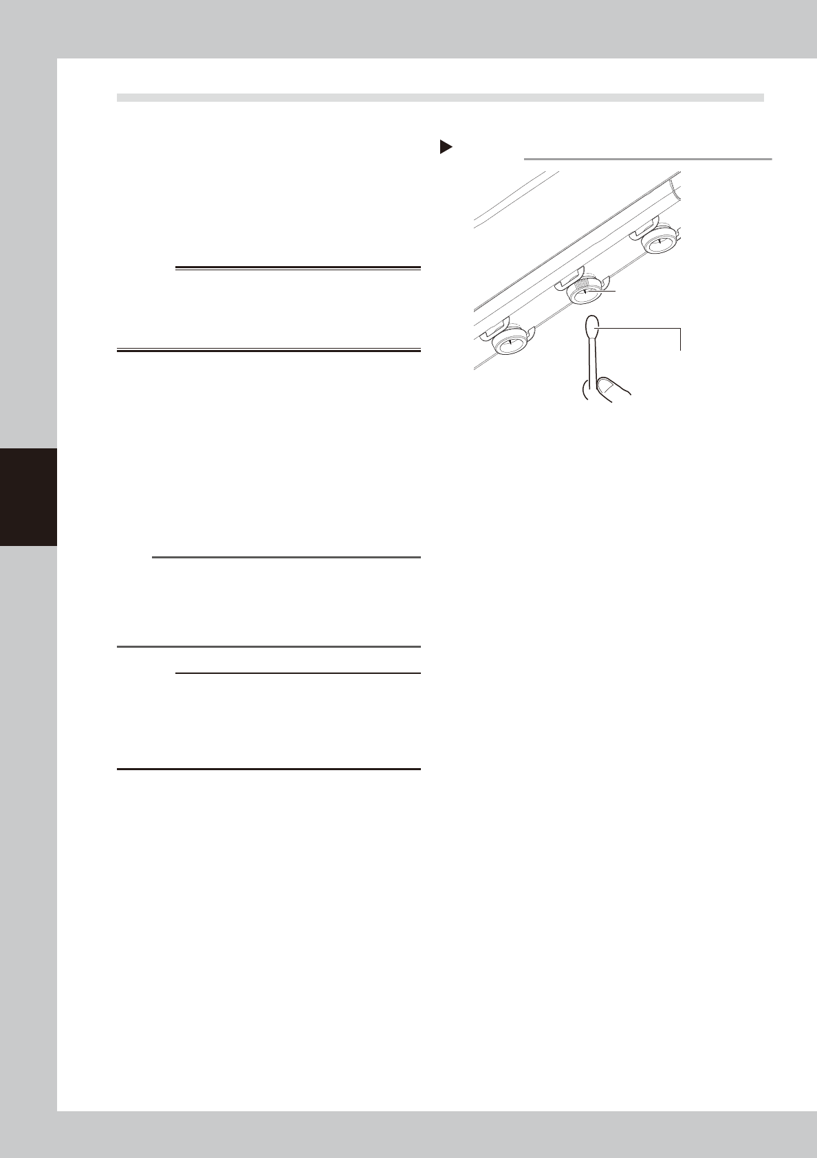
Clean the discharge needle.
1. Apply absolute ethanol to a cotton swab
slightly and clean the discharge needle.
2. Leave the cleaned discharge needle for
a while until it dries.
n
NOTE
It is also possible to clean the discharge needle by
detaching the discharge needle unit. See "1.2
Replacing the ionizer discharge needle (2-year)" on
next page for attaching and detaching the discharge
needle unit.
c
CAUTION
Do not dip the discharge needle unit to the absolute
ethanol when cleaning the detached discharge needle
unit. If applying a high voltage while absolute ethanol
remains in the unit, the ionizer main unit may be
damaged.
4
Supply the air and power on the
ionizer.
1. Turn the air supply/exhaust switch and
supply the air to the machine.
2. Close the machine safety cover and
press the [READY] button.
3.
Check that the green LED of the "POWER"
on the ionizer is turned on. Make sure that
no error is occurring.
Step 3
Cotton swab with
absolute ethanol
Cleaning the discharge needle
Discharge needle
53401-KMK-00
4-3
4
Maintenance of options
1.2 Replacing the ionizer discharge needle (2-year)
Replace ionizer discharge needle (KJX-M83P1-00X : NEEDLE SPARE SET/5 pcs) once every 2 years or if an error
still occurs even after performed "1.1 Cleaning the ionizer discharge needle (Monthly)". An Ionizer uses 10
discharge needles. As one each of ionizers are attached on front and rear of the machine if it is the front and rear
fixed bank type, 4 discharge needle units are required when performing maintenance work of machine.
1
Power off the ionizer.
1.
Press the emergency stop button and
then open the machine safety cover to
stop the power supply to the ionizer.
2.
Check that green LED of "POWER" on
ionizer is turned off.
w
WARNING
A VOLTAGE REMAINS ON THE DISCHARGE NEEDLE
IMMEDIATELY AFTER TURNING OFF POWER. BE AWARE
THAT TOUCHING DISCHARGE NEEDLE IMMEDIATELY AFTER
TURNING OFF POWER IS HAZARDOUS.
2
Turn off the air supply.
Turn the air supply/exhaust switch (valve) on
the lower left of the machine clockwise (EXT)
to turn off the main air.
3
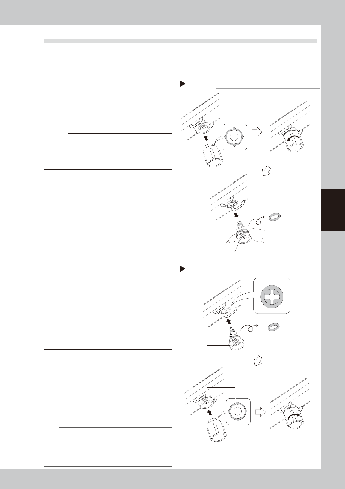
Detach the discharge needle unit.
1.
Insert the detaching tool, an ionizer
accessory, aligning the discharge needle
unit grooves.
2. Rotate the detaching tool
counterclockwise 1/8 of a turn.
3.
Detach the discharge needle unit.
4
Reattach the discharge needle unit.
1. Insert the discharge needle unit aligning
with the grooves of the ionizer.
2.
Insert the detaching tool aligning the
discharge needle unit grooves.
3. Rotate the detaching tool clockwise 1/8
of a turn.
c
CAUTION
The O-ring is in between the discharge needle unit and
ionizer. Make sure not to drop it.
5
Supply air and power on ionizer.
1. Turn the air supply/exhaust switch (valve)
and supply the air to the machine.
2. Close the machine safety cover and
press the [READY] button.
3.
Check that the green LED of the "POWER"
on the ionizer is turned on. Make sure that
no error is occurring.
n
NOTE
•
If continuing to receive error even after replacing
discharge needle unit, contact YAMAHA sales
representatives.
•
See the manufacturer's instructions for detailed
specifications of the ionizer.
Step 3
Aligning with grooves.
Make sure not to drop O-ring.
Detaching tool
Discharge needle unit
Removing the discharge needle unit
53402-KMK-00
Replacing the discharge needle unit
Step 4
Align with grooves.
Detaching tool
New discharge needle unit
Make sure not to drop O-ring.
Insertion port
53403-KMK-00
4-4
4
Maintenance of options
2. UPS (Uninterruptible Power Supply)
2.1 Replacing the UPS battery (3-year)
The battery is a consumable item. Even though the service life of the UPS may vary depending on the operating
environment, such as ambient temperature, it is recommended to replace the battery with a new one (KGA-
M6566-30X) at reference intervals of 3 years. The following describes how to replace the battery that is
incorporated into the UPS.
w
WARNING
BATTERY REPLACEMENTS SHOULD BE PERFORMED ONLY BY THOSE WITH ELECTRICAL WORK EXPERIENCE.
1
Power off the machine
Power off UPS several seconds after
powering off the machine.
w
WARNING
DO NOT ATTEMPT THIS BATTERY REPLACEMENT
PROCEDURE WHILE THE MACHINE IS IN THE EMERGENCY
STOP STATUS OR THE UPS FUNCTION IS RUNNING.
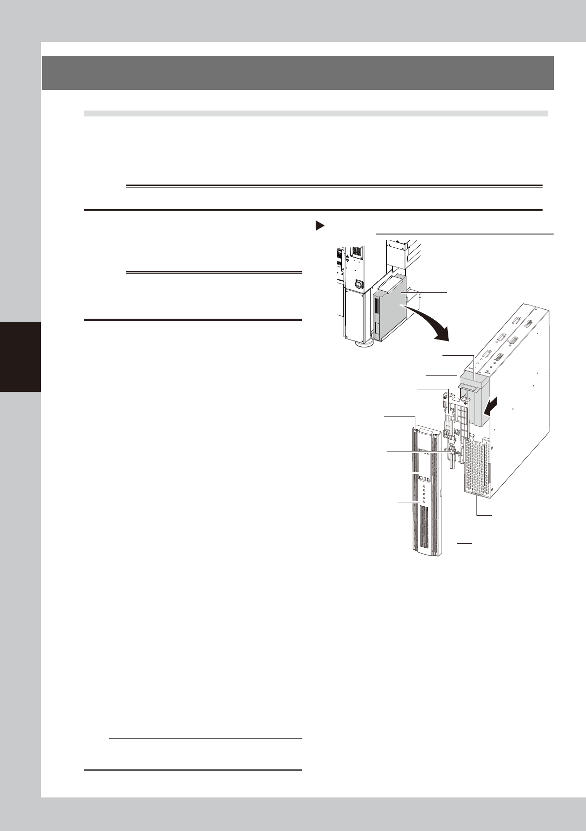
2
Remove the front panel.
Use a Phillips screwdriver to remove the
screws which mount the front panel, then
remove the front panel.
3
Disconnect the battery connector.
Disconnect the UPS side and internal battery
side connectors.
4
Remove the battery mounting
fixture.
Remove the battery fixture mounting screws,
then remove the battery mounting fixture.
5
Replace the removed battery with a
new one.
Extract the old battery and insert a new
battery in its place.
6
Reinstall the battery.
Reverse Steps 2 to 4 above to reinstall the
battery.
7
Check the UPS status.
1. Turn the machine power ON.
2. Press the ON button on the UPS operation
panel to check that the BATTERY LED is
OFF.
8
Write the battery replacement
year/month.
Write the battery replacement year/month
on the UPS WARNING label (see "Safety
instructions" in this manual).
n
NOTE
See the manufacturer's instructions for detailed
operation of the UPS.
Replacing UPS internal battery
UPS unit
Lower right portion on
front of machine
Internal battery
Internal battery
side connector
UPS side battery
connector
Battery mounting fixture
Front panel
Front panel hook
Battery mounting fixture
mounting screw
Front panel
mounting screws
UPS operation panel
Step 2-6
53404-KMK-00