00196497-07_SM_SXDX12_en.pdf - 第184页
Service Work Conveyor Conveyor 3.6.9 Changing Fixed Side Left/Right (EC Only) 184 Service Manual SIPLACE SX1/SX2/DX1/DX2 FS02 Converting the ad justment units: ► Loosen the screws (10) (2x two) fastening the two ad - jus…
Service Work Conveyor
3.6.9 Changing Fixed Side Left/Right (EC Only) Conveyor
Service Manual SIPLACE SX1/SX2/DX1/DX2 FS02 183
Conversion
Preparation:
► Use the software to move the conveyor side into the position which allows you best access to the
conveyor side for the work to be performed.
► Switch off the machine, disconnect it from the power supply and secure it to prevent unauthorized
reactivation. Observe the instructions in section "1.2 Preparatory Work..." [ ➙ 13].
► Pull the sensor rail off the guidance pins and place it in the conveyor.
► Push the carriage (8) under the two conveyor sides.
► Rotate the "side flange 2" by 180° and then screw the side flange back onto the carriage. Make sure
that the "side flange 2" (2) is fitted parallel on the carriage (8). Check their parallelism with an H scale.
This may not protrude anywhere.
► Fit the "side flanges 2" (2) from the outer side, onto the new flexible conveyor side.
► Fit the "side flanges fixed 1 and 2" (5) from the outer side, onto the new fixed conveyor side.
► Fix the "side flange fixed 1 and 2" (2) with the dowel pin to the conveyor base.
► Set the fixed side to the correct position.
(See "4.6.3.1 Setting the Fixed Conveyor Side on Single Conveyors" [ ➙ 280])
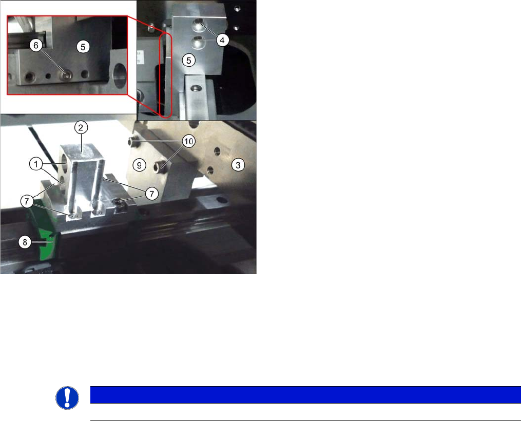
Refitting the brackets:
► Mark the installation points of the four brackets (2)
and (5), to make clear assignment easier later on.
► Loosen the screws (4) fastening the two "side flanges
fixed 1 and 2" (5) on the fixed side.
► Loosen the screws (6) fastening the two "side flanges
fixed 1 and 2" (5) on the conveyor base.
► Move the "side flanges fixed 1 and 2" (5) from the in-
put to the output area of the new fixed side.
► Loosen the screws (1) fastening the two "side flanges
2" (2) on the flexible side
(3).
► Disconnect the flexible side from the "side flanges 2"
(2).
► Loosen the screws (7) (2x four) fastening the two
"side flanges 2" on the carriage (8).
NOTICE
During refitting, the input and output sides are exchanged (left with right).
Service Work Conveyor
Conveyor 3.6.9 Changing Fixed Side Left/Right (EC Only)
184 Service Manual SIPLACE SX1/SX2/DX1/DX2 FS02
Converting the adjustment units:
► Loosen the screws (10) (2x two) fastening the two ad-
justment units (9).
► Move the adjustment units to the opposite side by
pulling on the width adjustment belt.
► Fit the adjustment units on the opposite side in the re-
verse order. Also observe the following instructions:
NOTICE!
Installation instructions
Make sure that the screws which were previously sealed
with locking varnish are once again sealed with locking
varnish.
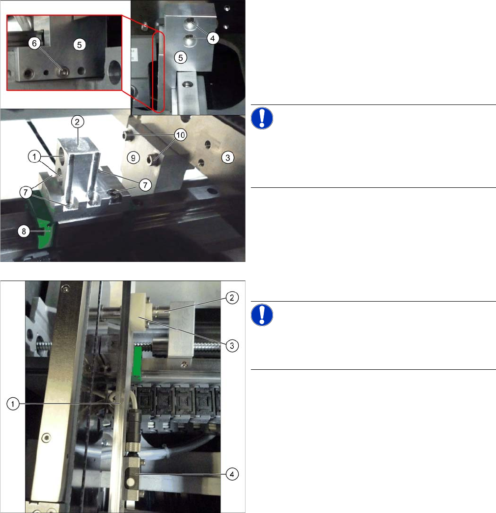
Converting the sensor rail (FS01 only):
NOTICE!
This work only needs to be performed on the conveyor
with FS01. It is not needed and no replacement tasks are
needed for conveyors with FS02.
► Push the sensor rail off the guidance pins (2).
► Dismantle the three sonar sensors (4) and fit these
again on the opposite side of the sensor rail (1). (fixed
side right to left side and fixed side left to right side)
► Dismantle the three plastic guidances (3) and fit
these again on the opposite side of the sensor rail.
► Run the sonar sensor cables accordingly on the op-
posite side. Make sure that these cables do not rub
against any parts and are not pinched.
► Fit the sensor rail onto the guidance pins.
► Check the setting of the sonar sensors and reteach
them, if required. (see "4.6.2 Teaching the Sonar
Sensor" [ ➙ 278]).
Service Work Conveyor
3.7.1 Replacing the Fixed/Guide Castors Component Trolley SX
Service Manual SIPLACE SX1/SX2/DX1/DX2 FS02 185
3.7
3.7 Component Trolley SX
Component Trolley SX
3.7.1
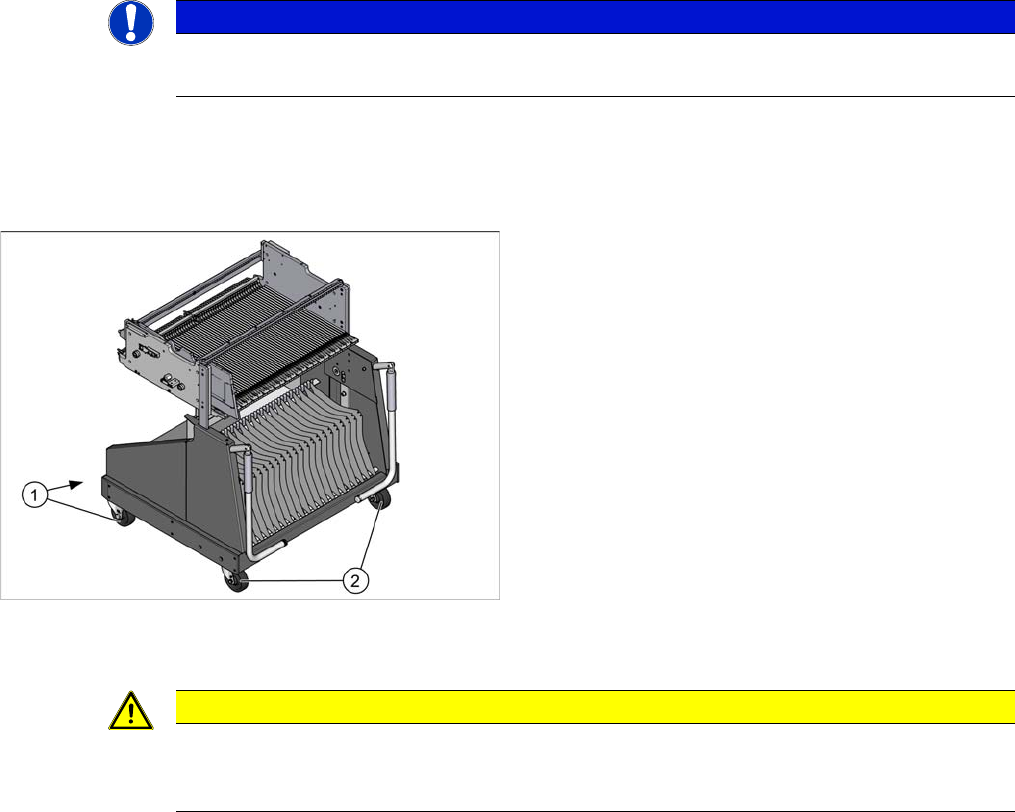
3.7.1 Replacing the Fixed/Guide Castors
Replacing the Fixed/Guide Castors
Parts, Equipment and Tools
Removal
► Move the changeover table out of the machine.
► Place the changeover table down on its side, on a suitable surface.
► Undo the screws fastening the fixed or guide castor to to replaced and then remove the castor.
Installation
► Follow the removal instructions in reverse order for installation.
NOTICE
SX and DX table
Unless specified otherwise, all specifications apply to both the SX and DX tables.
1. Fixed castor [03058705-xx]
2. Guide castor [03059198-xx]
CAUTION
Heavy machine part!
The changeover table must be placed on one side in order to remove the fixed/guide castors.
The changeover table is extremely heavy! You will need 2 people to perform this task