00196497-07_SM_SXDX12_en.pdf - 第195页
Service Work Conveyor 3.9.3 Removing the Front Section of the Manual Table Manual table Service Manual SIPLACE SX1/SX2/DX1/DX2 FS02 195 Removal ► Dismantle t he back section of the manual table. (See "3.9 .2 Rem ovi…
Service Work Conveyor
Manual table 3.9.3 Removing the Front Section of the Manual Table
194 Service Manual SIPLACE SX1/SX2/DX1/DX2 FS02
3.9.3
3.9.3 Removing the Front Section of the Manual Table
Removing the Front Section of the Manual Table
Parts, equipment and tools
▪ Rubber mallet
Overview
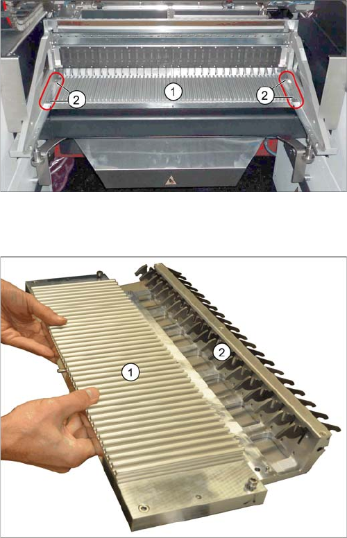
Manual table – front section (using the example of the
DX1/DX2)
1. Front part
2. Screws fastening the front section (4x)
1. Front part
2. Feeder locking device
This is fixed from below with 6 screws.
Service Work Conveyor
3.9.3 Removing the Front Section of the Manual Table Manual table
Service Manual SIPLACE SX1/SX2/DX1/DX2 FS02 195
Removal
► Dismantle the back section of the manual table. (See "3.9.2 Removing the Back Section of the Man-
ual Table" [ ➙ 193])
► Loosen the fastening screws of the feeder locking device and then remove the board.
► Loosen the 4 screws fastening the front section.
► Pull the module out of the locating pins. You may need to use a rubber mallet to help you.
Installation
► Follow the removal instructions in reverse order for installation.
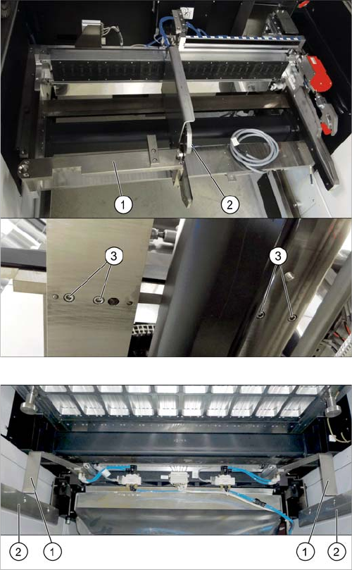
If there is a WPC at the same location, perform the follow-
ing two steps as well:
► Dismantle the WPC docking rail (1).
► Dismantle the left side of the insert mechanism (2).
Loosen the 4 fastening screws (3) on the underside
and the 2 fastening screws on the top of the empty
tape duct.
► Dismantle the stoppers (1).
You may need to lower the cutter onto the support
plates (2). (See "3.11.1 Replacing the Cutter
[03063781Sxx]" [ ➙ 223])
Service Work Conveyor
Manual table 3.9.4 Replacing the Locking Latch [03069205-xx]
196 Service Manual SIPLACE SX1/SX2/DX1/DX2 FS02
3.9.4
3.9.4 Replacing the Locking Latch [03069205-xx]
Replacing the Locking Latch [03069205-xx]
Please refer the instructions in section "3.7.4 Replacing the Locking Latch [03069205-xx]" [ ➙ 188].
See also
3.9.5.1 Operating the Unlocking Hook [ ➙ 198]
3.9.8 Replacing the Feeder Lock on the Manual Table [03082778-xx] [ ➙ 202]
3.9.5
3.9.5 Replacing the Feeder Control Unit (FCU)
Replacing the Feeder Control Unit (FCU)
Parts, equipment and tools
Select the correct spare part:
▪ Rubber mallet
Overview
NOTICE
Only every second location can be occupied.
We recommend that you use 2x8 mm feeders.
If you are using single 8 mm feeders, the location next to the feeder will be left empty.
NOTICE
Remove the feeder
Also observe section "3.9.5.1 Operating the Unlocking Hook" [ ➙ 198].
Machine type Designation Item No.
DX4 FCU 03082687-xx
DX1/DX2 FCU 03082605-xx
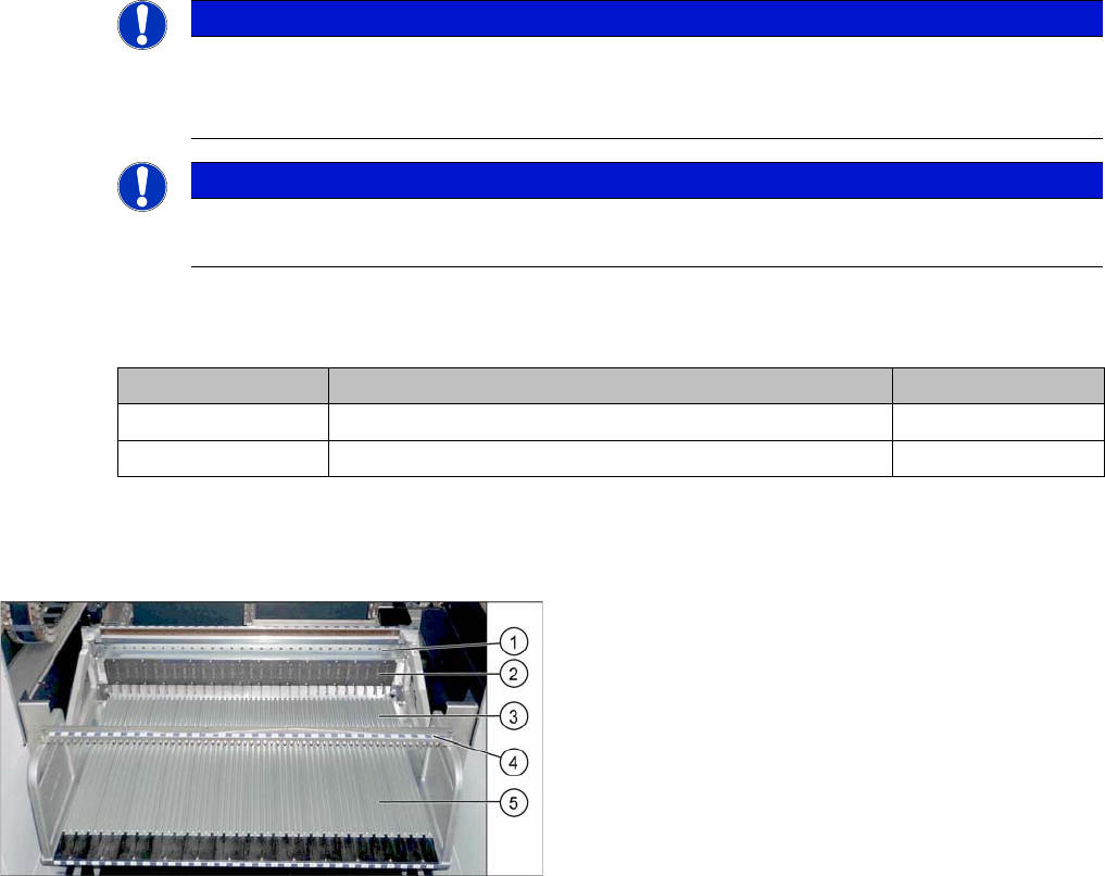
Manual table (using example of DX1/DX2)
1. Centering bar
2. FCU
3. Front part
4. Fixture bar
5. Back part