00196497-07_SM_SXDX12_en.pdf - 第72页
Service Work Conveyor Control 3.3.3 Replacing the Control Computer BoxPC 72 Service Manual SIPLACE SX1/SX2/DX1/DX2 FS02 3.3.3 3 . 3 . 3 R e p la c in g t h e C o n t r o l C o m p u t e r B o x P C Replacing the Control …

Service Work Conveyor
3.3.2 Replacing the I/O Control Unit [03116049-xx] Control
Service Manual SIPLACE SX1/SX2/DX1/DX2 FS02 71
Removal
► Take a note of the component counter reading at the software user interface.
► Switch off the machine, disconnect it from the power supply and secure it to prevent unauthorized
reactivation. Observe the instructions in section "1.2 Preparatory Work..." [ ➙ 13].
► Unplug all press-fit connections. You may want to mark the positions, to make clear assignment eas-
ier later on.
► Pull the I/O control unit out of its mount.
Installation
► Follow the removal instructions in reverse order for installation. Also observe the following instruc-
tions:
CAUTION
Installation instructions
► Make sure that the DIP switches are configured correctly (see "5.1.3 I/O control unit
[03116049-xx]" [ ➙ 303]).
► Check if the component counter of the software still matches the value you have written
down. If this is not the case, contact SIPLACE service.
Service Work Conveyor
Control 3.3.3 Replacing the Control Computer BoxPC
72 Service Manual SIPLACE SX1/SX2/DX1/DX2 FS02
3.3.3
3.3.3 Replacing the Control Computer BoxPC
Replacing the Control Computer BoxPC
Parts, Equipment and Tools
▪ Machines Up To Serial Number Mxxx:
– BoxPC 627B with hotlink cable [03084494-xx] or
– Control Computer BoxPC 627C [03094731Sxx] (station computer and 3D Coplan option)
▪ Machines from Serial Number N001:
– BoxPC ABP402-A CPU1020E 2xPCI SSD-80GB [03120423-xx] (iBase)
1)
Please note that the new CAN card may need a new driver. Observe the instructions in section "4.3.4
Installing the CAN Card Driver" [ ➙ 258].
▪ Installation Manual Windows Embedded Standard 7 [00197737-xx]
Overview
NOTICE
Additional hardware for the BoxPC
The BoxPC is supplied without the following parts. If required, these must be removed from the
old BoxPC and fitted in the new one or ordered as new parts:
DX1/DX2,
SX1/SX2 up to Mxxx
SX1/SX2 from N001
Hotlink Interface PCI-A24-K01 [03052135-xx]
Hotlink interface/Power cable [03042074-xx]
CAN card CAN card PowerCAN-
PCI [03079973-xx]
1)
(replaces:
03052590-xx])
The CAN interface CINX takes over this task (see
Replacing the CAN Interface CINX [03108598-xx]
(from machine no.: N001))
RAM See "3.3.7 Replacing the RAM in the BoxPC" [ ➙ 80]
Ethernet adapter Permanently installed Permanently installed
If a 3D Coplan or a barcode scanner is installed, the
"LAN card PCI Gigabit SEMPRE NC1000-1"
[03112190-xx] is needed in addition.
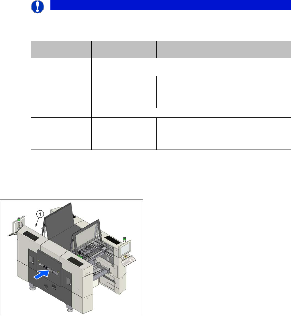
The BoxPC (1) can be found at the top right of location 2.
Service Work Conveyor
3.3.3 Replacing the Control Computer BoxPC Control
Service Manual SIPLACE SX1/SX2/DX1/DX2 FS02 73
BoxPC ABP402-A CPU1020E 2xPCI SSD-80GB (iBase) [03120423-xx] - from machine no.: N001
Removal
► Take a note of the component counter reading at the software user interface.
► Switch off the machine, disconnect it from the power supply and secure it to prevent unauthorized
reactivation. Observe the instructions in section "1.2 Preparatory Work..." [ ➙ 13].
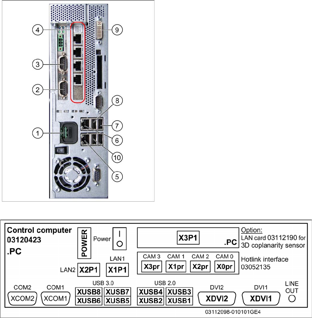
► Unplug all press-fit connections to the BoxPC. Mark their positions, to make clear assignment easier
later on.
BoxPC 627C [03094731-xx] – up to machine no.: Mxxx
1. Power supply DC 24 V
2. CAN 1 on the CAN bus card
3. CAN 2 on the CAN bus card
4. Hotlink card
5. LAN 2 – connection to Vision computer
(optional second BoxPC 3D Coplan)
6. LAN 1 – connection to SIPLACE Pro
(connection to line hub)
7. USB 0 – connection for keyboard/touchscreen (con-
nection to USB hub)
8. USB 2 – connection for an external DVD drive
9. DVI/VGA monitor connection
(connection to video multiplexer)
10. USB video multiplexer