00196497-07_SM_SXDX12_en.pdf - 第230页
Service Work Conveyor Cutter 3.11.3 Replacing the Articulated Joint on the Short-Strok e Cylinder [03058685-xx] 230 Service Manual SIPLACE SX1/SX2/DX1/DX2 FS02 ► Unp lug the elec trical connec tions (2) from th e valves …
Service Work Conveyor
3.11.3 Replacing the Articulated Joint on the Short-Stroke Cylinder [03058685-xx] Cutter
Service Manual SIPLACE SX1/SX2/DX1/DX2 FS02 229
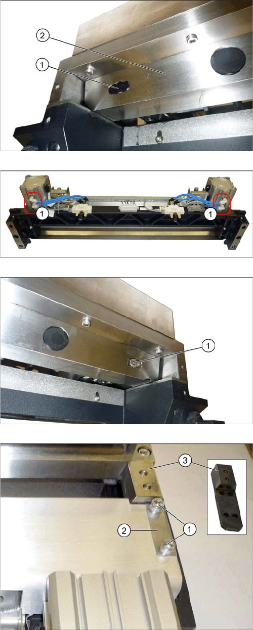
► Remove the two screw covers (1) [03080355-xx] on
the left and right of the moveable blade (2).
► Unplug the pneumatic hoses (1) below the short-
stroke cylinder. Mark their positions, to make clear
assignment easier later on.
► Remove the two screws (1) fastening the articulated
joints on the short-stroke cylinders.
The moveable blades have now been de-coupled.
► Undo the 4 screws (1) fastening the cover on the left
and right and then remove the two shim plates (2).
► Remove the two guidances (3) on the left and right
sides.
Service Work Conveyor
Cutter 3.11.3 Replacing the Articulated Joint on the Short-Stroke Cylinder [03058685-xx]
230 Service Manual SIPLACE SX1/SX2/DX1/DX2 FS02
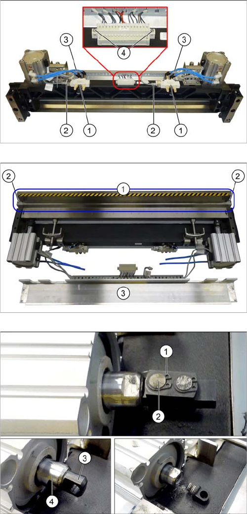
► Unplug the electrical connections (2) from the
valves (1).
► Unplug the pneumatic hoses (3) from the valves.
Mark their positions, to make clear assignment easier
later on.
► Remove the two fastening screws on the terminal
strip.
The terminal strip is now only connected to the cables.
► Swing the top cover (3) forwards.
► Loosen the circlip (1).
► Push the piston rod a little into the short-stroke cylin-
der and rotate the articulated joint by 90 degrees.
► Push the bolt (2) out of the articulated joint.
► Unscrew the remaining articulated joint adapter (3)
from the piston (4).
Service Work Conveyor
3.11.3 Replacing the Articulated Joint on the Short-Stroke Cylinder [03058685-xx] Cutter
Service Manual SIPLACE SX1/SX2/DX1/DX2 FS02 231
Installation
► Follow the removal instructions in reverse order for further installation. Also observe the following
instructions:
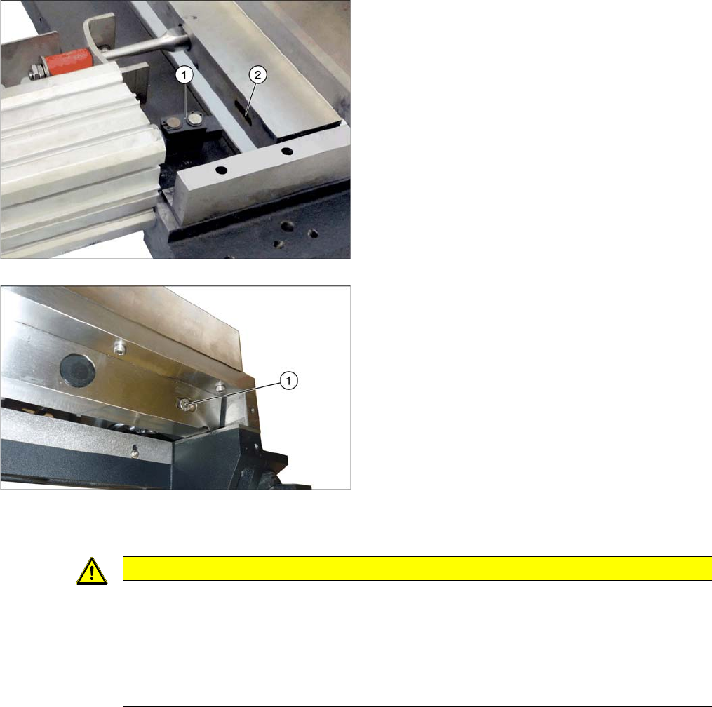
► Screw the articulated joint (1) into the short-stroke
cylinder with a torque of 22 Nm. Make sure that the
joint is horizontal so that it fits into the recess (2) in the
moveable blade. Secure the screw with Loctite 243.
► Screw the articulated joint to the moveable blades.
Tighten the screws to a torque of 8.8 Ncm.
CAUTION
Installation instructions
► Secure with screws with Loctite.
► Insert the new screw caps. Remove the protruding plastic residues with a knife.
► Hook the waste tape chute into place. Please also observe section "3.10.10 Replacing the
Waste Tape Chute" [ ➙ 221]. Pay particular attention to the plastic strips and the fuses (if
present).