00196497-07_SM_SXDX12_en.pdf - 第67页
Service Work Conveyor 3.2.18 Indicator Lamp and Lig ht Elements Electrical System Service Manual SIPLACE SX1/SX2/DX1/DX2 FS02 67 Conversion 2-/3-Par t Indicator Lamp Parts, Equipment and Tools ▪ For converting a two-part…
Service Work Conveyor
Electrical System 3.2.18 Indicator Lamp and Light Elements
66 Service Manual SIPLACE SX1/SX2/DX1/DX2 FS02
3.2.18.2
3.2.18.2 Replacing the Indicator Lamp (Variant 2)
Replacing the Indicator Lamp (Variant 2)
Parts, Equipment and Tools
▪ Tower light standard [03103121-xx]
Overview
Removal
► Switch off the machine, disconnect it from the power supply and secure it to prevent unauthorized
reactivation. Observe the instructions in section "1.2 Preparatory Work..." [ ➙ 13].
► Remove the monitor. Unplug all electrical connections and undo the screws fastening the monitor to
its holder.
► Loosen the two screws on the holder [03116272Sxx].
► Pull the indicator lamp with its retaining bracket up and out of the holder.
► Unplug the indicator lamp.
Installation
► Installation is performed by following the above instructions in the reverse order.
When inserting the light element, observe the identification on the casing.
► Check the function of the indicator lamp.
NOTICE
Two- and three-part fault indicator lamp
The fault indicator lamp consists of a green basic module and can be configured as a two-part
version a three-part version:
► Light tower two colors [00519895Sxx] (with an additional white continuous light element)
► Light tower three colors [00519896Sxx] (with an additional red and yellow continuous light
element)
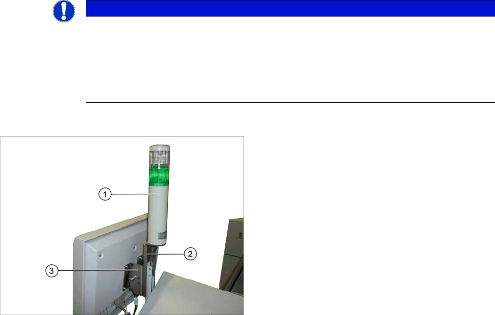
1. Indicator lamp (variant 2)
2. Indicator lamp retaining bracket
3. Monitor holder
The retaining bracket of the indicator lamp is fixed to the
monitor holder by means of fastening screws.

Service Work Conveyor
3.2.18 Indicator Lamp and Light Elements Electrical System
Service Manual SIPLACE SX1/SX2/DX1/DX2 FS02 67
Conversion 2-/3-Part Indicator Lamp
Parts, Equipment and Tools
▪ For converting a two-part lamp into a three-part one:
Light tower three colors [00519896Sxx]
▪ For converting a three-part lamp into a two-part one:
Light tower two colors [00519895Sx]
Procedure
► Switch off the machine, disconnect it from the power supply and secure it to prevent unauthorized
reactivation. Observe the instructions in section "1.2 Preparatory Work..." [ ➙ 13].
You can individually lift off each color segment (= base unit) of the indicator lamp.
► Lift off the white color segment with a short rotation.
► Insert the new color segments and new light elements, if necessary.
When inserting the light elements, observe the identification on the casing.
► Attach the yellow and the green color segment with a short rotation.
► Check the function of the indicator lamp.
3.2.18.3
3.2.18.3 Replacing the Light Elements in the Indicator Lamp
Replacing the Light Elements in the Indicator Lamp
SXDX12V1V2 - Note
Parts, Equipment and Tools
▪ Incandescent lamp BA15d 24V/5W [03005204-xx]
or
LED bulb socket B15d 24V AC/DC clear [03099236-xx]
Removal/Installation
► Switch off the machine, disconnect it from the power supply and secure it to prevent unauthorized
reactivation. Observe the instructions in section "1.2 Preparatory Work..." [ ➙ 13].
You can individually lift off each color segment (= base unit) of the indicator lamp.
► Lift off the relevant color segment with a short rotation.
► Remove the light element and insert a new one.
When inserting the light element, observe the identification on the casing.
► Re-attach the yellow and the green color segment with a short rotation.
► Check the function of the indicator lamp.
NOTICE
Description example
The following section describes the conversion of a two-part lamp into a three-part lamp. The
conversion of a three-part lamp into a two-part lamp is identical.
NOTICE
Variant 1 only
This section describes the replacement of light elements on indicator lamps of variant 1.
Service Work Conveyor
Control 3.3.1 Replacing the Video Multiplexer Splitter / VGA Splitter Cable (Machine Nos.:
68 Service Manual SIPLACE SX1/SX2/DX1/DX2 FS02
3.3
3.3 Control
Control
See also
5 Description of the Circuit Boards [ ➙ 299]
3.3.1
3.3.1 Replacing the Video Multiplexer Splitter / VGA Splitter Cable (Machine Nos.: Kxxx/Lxxx/Mxxx only)
Replacing the Video Multiplexer Splitter / VGA Splitter Cable (Machine Nos.: Kxxx/
Lxxx/Mxxx only)
Parts, Equipment and Tools
The video multiplexer splitter [03057965-xx] is replaced by a new video splitter. In case of replacement,
you need the following spare part kit:
▪ Spare Part Kit VGA Splitter Cable [03082983-xx]
Contents:
– 1x splitter cable VGA 2 port [03076910-xx]
– 1x mini gender changer HD15 Bu - HD15 Bu [03082986-xx]
– 1x USB extension cable A-St - A-Bu 1.5 m [03074536-xx]
– 20x cable tie (B = 3.6 mm, L = 140 mm) TY 24M [00805141-xx]
You need the following tools for this:
▪ Allen key, size 2.5
▪ Diagonal cutters
Removal
NOTICE
For machine nos.: Kxxx, Lxxx und Mxxx only
From machine no.: N001 upwards, the cables are plugged in directly into the BoxPC.
► Switch off the machine, disconnect it from the power
supply and secure it to prevent unauthorized reacti-
vation. Observe the instructions in section "1.2 Pre-
paratory Work..." [ ➙ 13].
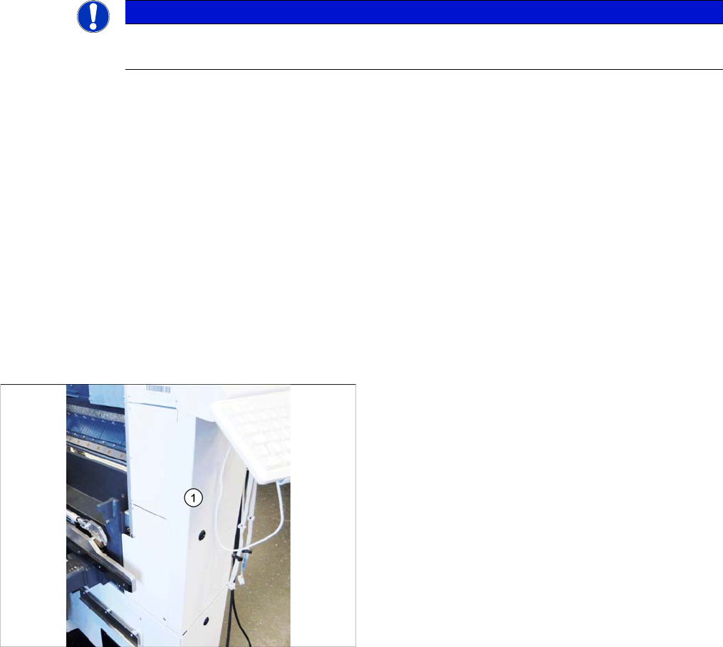
► At location 2, open the cover below the monitor.