00196497-07_SM_SXDX12_en.pdf - 第301页
Description of the Circuit Boards 5.1.2 GCU/MGCU Electrics and Control Service Manual SIPLACE SX1/SX2/DX1/DX2 FS02 301 5.1.2 5 . 1 . 2 G C U / M G C U GCU/MGCU 5.1.2.1 5 . 1 . 2 . 1 C o n t r o l m o d u le G C U - C M […
Description of the Circuit Boards
Electrics and Control 5.1.1 CAN switch [03083844-xx]
300 Service Manual SIPLACE SX1/SX2/DX1/DX2 FS02
DIP switch S1.3 - S1.5 error frame limits [03083844-02]
Button S2 [03083844-02]
S1.3 S1.4 S1.5 Function
OFF OFF OFF 1 error frame
ON OFF OFF 5 error frames/min
OFF ON OFF 10 error frames/min
ON ON OFF 10 error frames/h
OFF OFF ON 50 error frames/h
ON OFF ON 100 error frames/h
OFF ON ON 500 error frames/h
Buttons Status Signal name Description
S2 When pressed SWITCH_TACT Reset error frame
Description of the Circuit Boards
5.1.2 GCU/MGCU Electrics and Control
Service Manual SIPLACE SX1/SX2/DX1/DX2 FS02 301
5.1.2
5.1.2 GCU/MGCU
GCU/MGCU
5.1.2.1
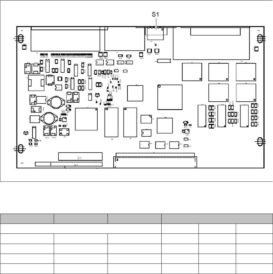
5.1.2.1 Control module GCU-CM [03060951-xx]
Control module GCU-CM [03060951-xx]
03060951-03
This board is fitted in the GCU.
Dip switch S1 [03060951-03]
Switch Status Signal name Description
GCU1 GCU2 GCU3
S1.1 ON/OFF Portal_ID_0 ON OFF OFF
S1.2 ON/OFF Gantry_ID_1 OFF OFF ON
S1.3 ON/OFF Portal_ID_2 ON OFF ON
S1.4 ON/OFF Portal_ID_3 OFF OFF OFF
Description of the Circuit Boards
Electrics and Control 5.1.2 GCU/MGCU
302 Service Manual SIPLACE SX1/SX2/DX1/DX2 FS02
5.1.2.2
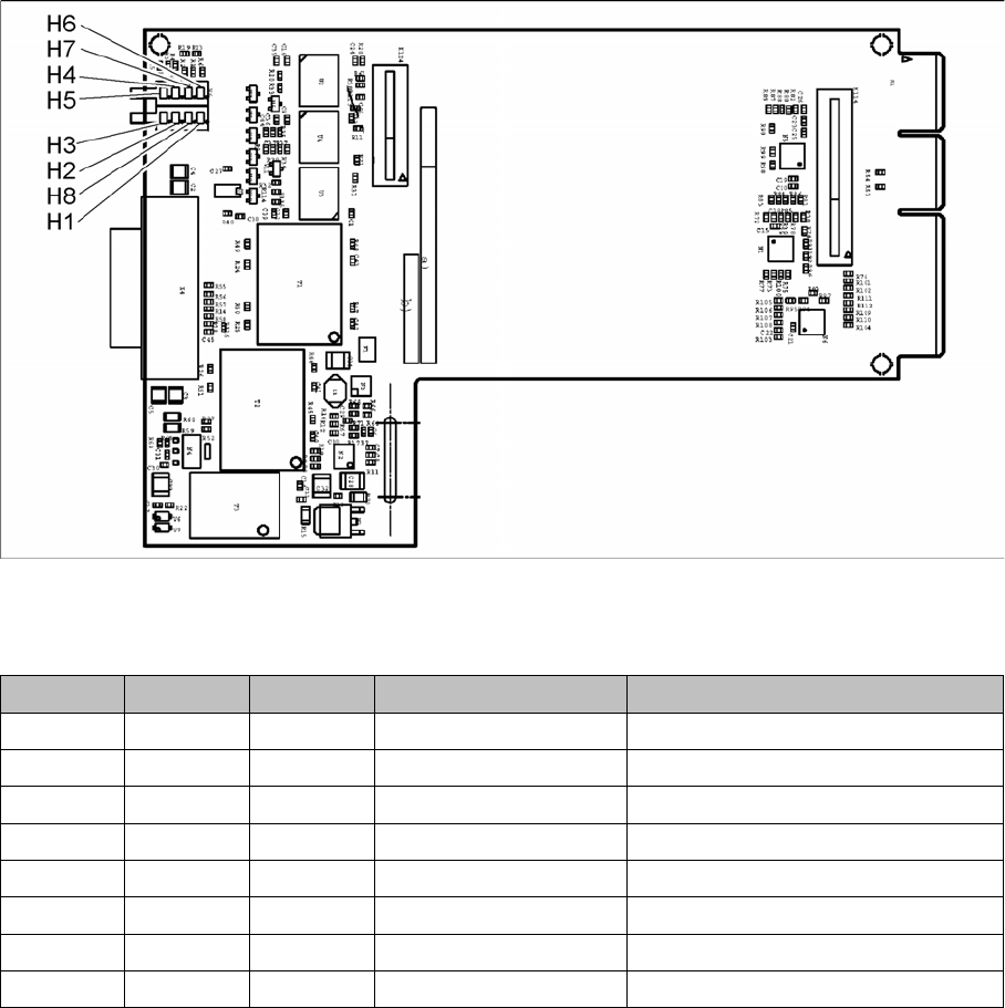
5.1.2.2 Diagnosis interface [03075813-xx]
Diagnosis interface [03075813-xx]
03075813-01
This board is fitted in the GCU.
LED [03075813-01]
LED Color Status Signal name Description
H1 RD ON LED_ERROR Error display
H2 GN ON A1_LED_PM_ON_N Power module activated, axis 1
H3 GN ON A2_LED_PM_ON_N Power module activated, axis 2
H4 GN ON A1_LED_END End position signal, axis 1
H5 GN ON A2_LED_END End position signal, axis 2
H6 GN ON LED_READY Ready
H7 GN ON P24V +24VDC
H8 GN ON P5V +5VDC