00196497-07_SM_SXDX12_en.pdf - 第265页
Settings 4.4.3 Checking Track Signals and Zero Pulse Gantry Settings Service Manual SIPLACE SX1/SX2/DX1/DX2 FS02 265 4.4.3.1 4 . 4 . 3 . 1 T r a c k S ig n a ls a n d Z e r o P u ls e Track Signals and Zero Pulse SX12? C…
Settings
Gantry Settings 4.4.3 Checking Track Signals and Zero Pulse
264 Service Manual SIPLACE SX1/SX2/DX1/DX2 FS02
4.4.3
4.4.3 Checking Track Signals and Zero Pulse
Checking Track Signals and Zero Pulse
The zero pulse must be reliably and clearly recognized by the read head. To ensure this, you can check
the analog zero pulse. Electronically controlled settings can not be performed on the incremental length
measurement system.
Parts, equipment and tools
▪ Read head test device [03071361-xx]
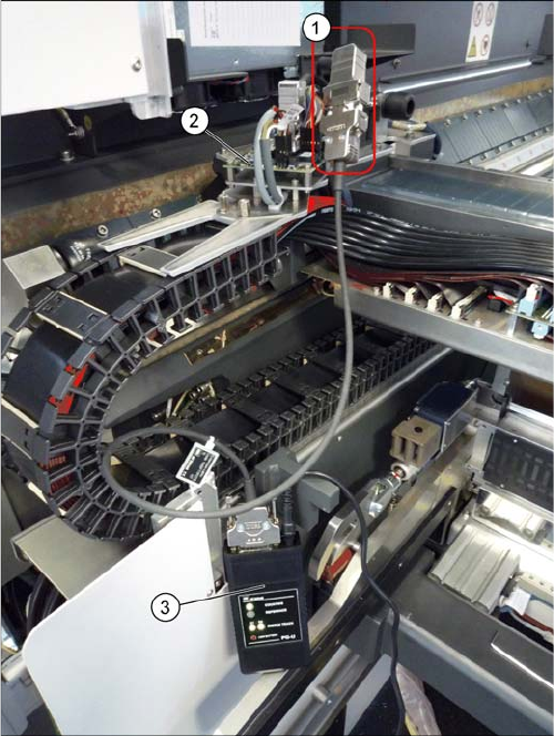
Check
► Connect the testing device with the signal generator.
To do this, unplug the signal generator from the sen-
sor module and connect it to the testing device.
► Move the axis manually.
Keep an eye on the COUNTING and REFERENCE
LEDs.
⇨ When the setting is correct, the COUNTING LED
should always shine green and the REFERENCE
LED should flash green each time the zero pulse
is passed.
⇨ When the setting is not correct, the COUNTING
LED will shine red and the REFERENCE LED will
be red or orange (orange = just outside the toler-
ance).
Settings
4.4.3 Checking Track Signals and Zero Pulse Gantry Settings
Service Manual SIPLACE SX1/SX2/DX1/DX2 FS02 265
4.4.3.1
4.4.3.1 Track Signals and Zero Pulse
Track Signals and Zero Pulse
SX12?
Checking the connector on the testing device
Check
Proceed as follows to check the zero pulse.
► Switch off the machine.
► Unplug the incremental encoder from the head board or the gantry interface and connect it to the
test device. (See "4.4.3.1.1 Test Device PG1-I (MS22/MS30) [03102699-xx] – Operation" [ ➙ 266])
► Move the head or gantry manually back and forth. This movement enables you to read the correct
track signal progress from the test device.
► If the track signal is not within the tolerance range, you will need to reset the incremental encoder.
The incremental encoder has then been fitted either too near, too far away, inclined and/or displaced.
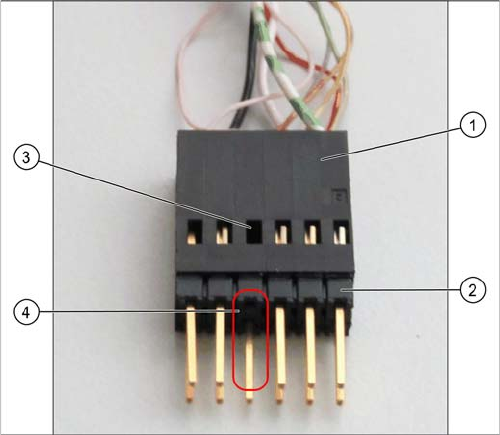
► Make sure that the pin adapter (2) is fitted correctly
on the connector (1) of the testing device.
You should not be able to see any cable in the
opening (3) in place of the missing pin (4).

Settings
Gantry Settings 4.4.3 Checking Track Signals and Zero Pulse
266 Service Manual SIPLACE SX1/SX2/DX1/DX2 FS02
Test Device PG1-I (MS22/MS30) [03102699-xx] – Operation