00196497-07_SM_SXDX12_en.pdf - 第42页
Service Work Conveyor Electrical System 3.2.4 Checking the Input Voltage on the Transf ormer Module 42 Service Manual SIPLACE SX1/SX2/DX1/DX2 FS02 3.2.4 3 . 2 . 4 C h e c k in g t h e I n p u t V o lt a g e o n t h e T r…
Service Work Conveyor
3.2.3 Checking the Input Voltage at the Inrush Current Limitation Board (A1) Electrical System
Service Manual SIPLACE SX1/SX2/DX1/DX2 FS02 41
3.2.3
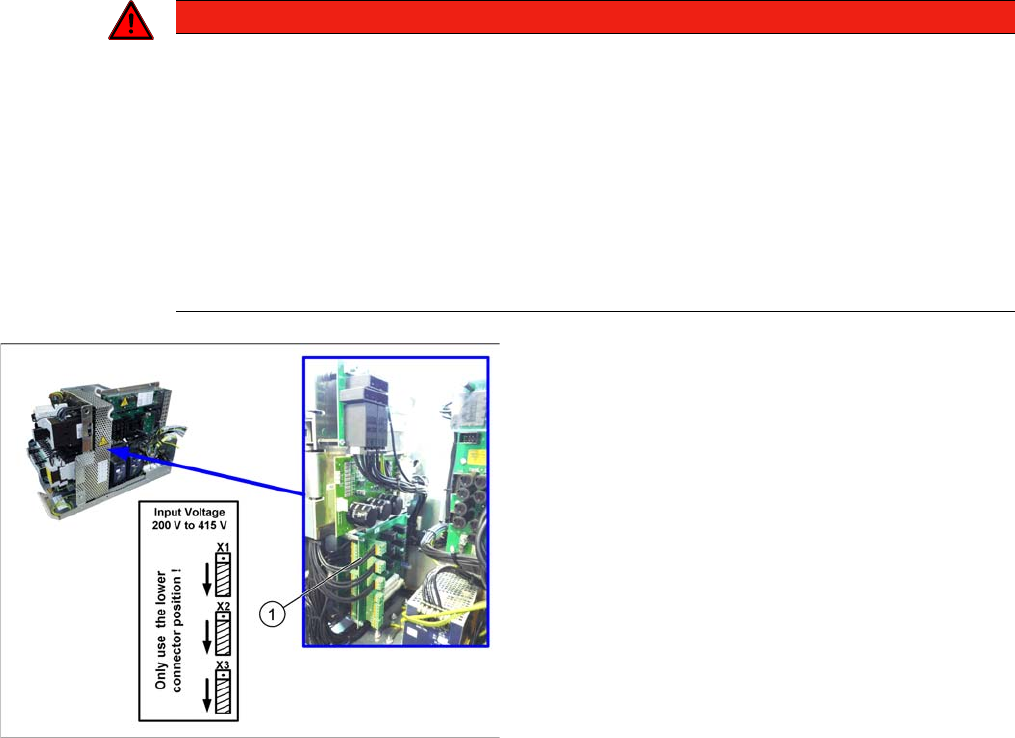
3.2.3 Checking the Input Voltage at the Inrush Current Limitation Board (A1)
Checking the Input Voltage at the Inrush Current Limitation Board (A1)
DANGER - Voltages (wit hout SMPS)
Checking/setting
► Remove the mesh cover on the boards. To do this, loosen the four screws on the side of the cover.
► Check the jumper arrangement and correct if necessary.
Take note of the position of jumper J1 (see "5.1.5 Inrush Current Limitation Board Transformer (A1)
[03066830-xx]" [ ➙ 310]).
► Fit the protective grid back into place.
See also
1.1.3 Safety Instructions for the Power Supply [ ➙ 10]
DANGER
Voltages
There is a risk of dangerous touch voltages and short circuits occurring in power supplies which
have been made accessible and are connected for measurement purposes or bridge circuit
control.
Nonobservance of these safety instructions may cause injury to personnel and damage to the
machine!
Measurements may only be performed by specially trained service technicians, with appropri-
ate qualifications and expertise.
► Observe the instructions in section Safety Instructions for the Power Supply (Without
SMPS).
1. Board A1 for the inrush current limitation board of the
transformer
X1, X2, X3: plug-in jumpers to configure the inrush cur-
rent limitation
The inrush current limitation board must be set to 400 V,
irrespective of the supply voltage. This is performed with
the help of plug-in jumpers on the inrush current limitation
board (1).
► Check the jumper assignments and correct these,
where necessary.
Service Work Conveyor
Electrical System 3.2.4 Checking the Input Voltage on the Transformer Module
42 Service Manual SIPLACE SX1/SX2/DX1/DX2 FS02
3.2.4
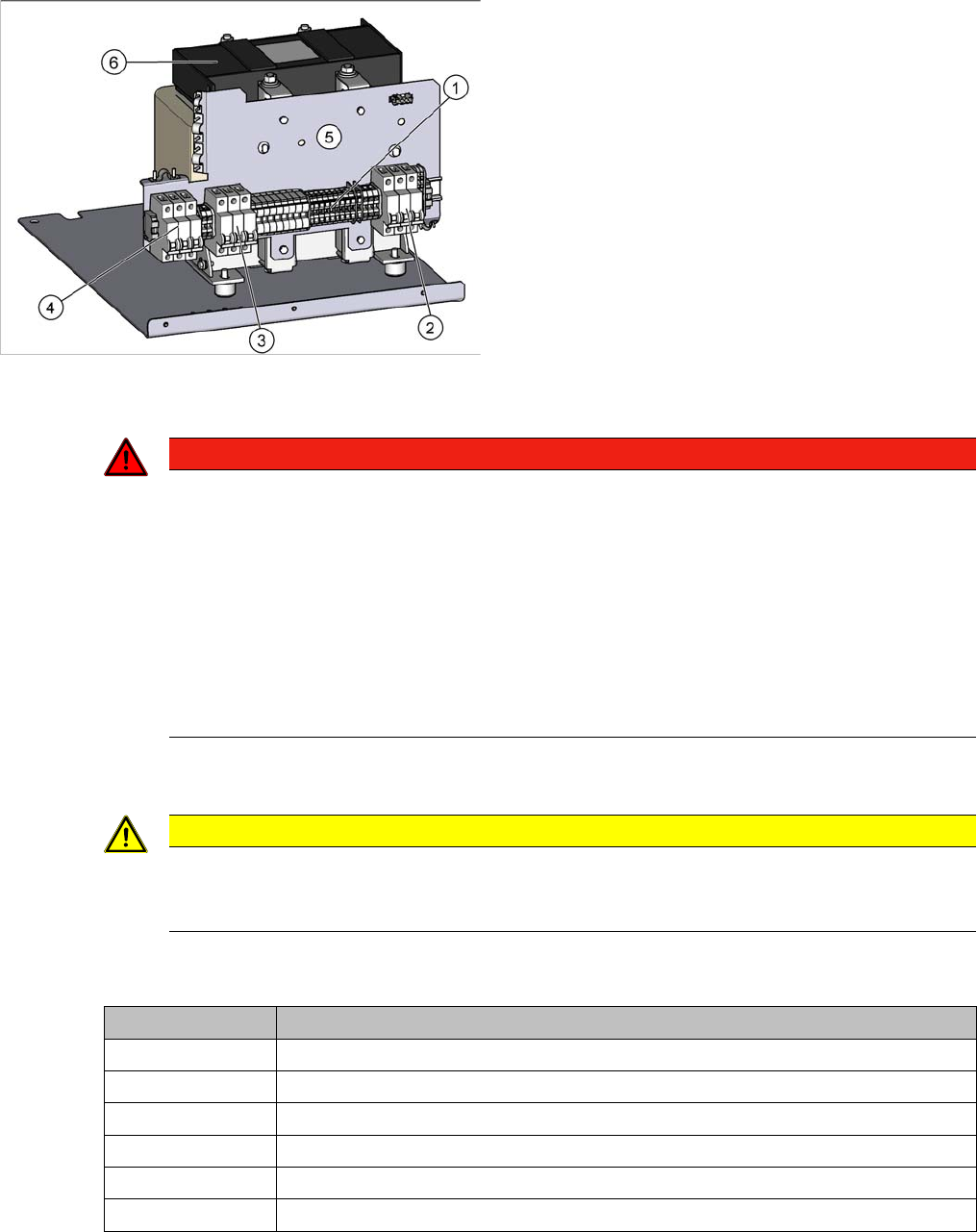
3.2.4 Checking the Input Voltage on the Transformer Module
Checking the Input Voltage on the Transformer Module
The primary end of the three-phase transformer needs to be configured for the respective supply voltage.
Procedure
DANGER - Voltages (wit hout SMPS)
► Check the terminal panel (1), to make sure that the primary end of the three-phase transformer (ca-
ble to (2)) is connected correctly for the required supply voltage.
The following overview shows the connection options for the primary voltages of the three-phase trans-
former:
See also
1.1.3 Safety Instructions for the Power Supply [ ➙ 10]
1. Terminal panel with primary connections for the
three-phase transformer
2. Fuses
3. Fuses
4. Fuses
5. Installation position for the electrics of the vacuum
pump option
6. Three-phase transformer
DANGER
Voltages
There is a risk of dangerous touch voltages and short circuits occurring in power supplies which
have been made accessible and are connected for measurement purposes or bridge circuit
control.
Nonobservance of these safety instructions may cause injury to personnel and damage to the
machine!
Measurements may only be performed by specially trained service technicians, with appropri-
ate qualifications and expertise.
► Observe the instructions in section Safety Instructions for the Power Supply (Without
SMPS).
CAUTION
3x 200 V, 3x 208 V
The Japanese power supply network (3x 200 V~) and the power supply networks in the USA
(3x 208 V~) are connected to the terminals for 3x 204 V~.
Terminal panel Voltage
1U1, 1V1, 1W1 415 VAC
3U3, 3V3, 3W3 400 VAC
4U4, 4V4, 4W4 380 VAC
5U5, 5V5, 5W5 230 VAC
6U6, 6V6, 6W6 220 VAC
7U7, 7V7, 7W7 204 VAC
Service Work Conveyor
3.2.5 Replacing the AC/DC Converter (PS1) 25 V [03055232-xx] Electrical System
Service Manual SIPLACE SX1/SX2/DX1/DX2 FS02 43
3.2.5
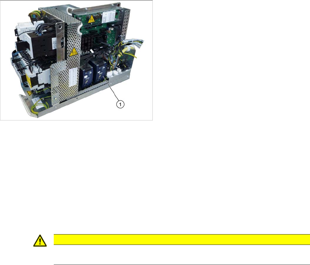
3.2.5 Replacing the AC/DC Converter (PS1) 25V [03055232-xx]
Replacing the AC/DC Converter (PS1) 25 V [03055232-xx]
Parts, equipment and tools
▪ AC/DC converter DC24V/20A 3 phase, set to DC25V [03055232-xx]
Overview
Removal
► Switch off the machine, disconnect it from the power supply and secure it to prevent unauthorized
reactivation. Observe the instructions in section "1.2 Preparatory Work..." [ ➙ 13].
► Unplug all connections to the module. You may want to mark their positions, to make clear assign-
ment easier later on.
► To release the module, press the lever at the back of the module down and then pull the module off
the rail.
Installation
► Follow the removal instructions in reverse order for installation. Also observe the following instruc-
tions:
1. AC/DC converter (PS1) 25 V
CAUTION
Installation instructions
► Set the voltage to 25 V. (See "4.3.2 Setting the Voltage on the AC/DC Converters" [➙255])