00196497-07_SM_SXDX12_en.pdf - 第237页
Service Work Conveyor 3.11.5 Replacing the Cutter Blades Cutter Service Manual SIPLACE SX1/SX2/DX1/DX2 FS02 237 Installation – preparations ► Clean all parts and th e cutter before insta llation. Observe the following po…
Service Work Conveyor
Cutter 3.11.5 Replacing the Cutter Blades
236 Service Manual SIPLACE SX1/SX2/DX1/DX2 FS02
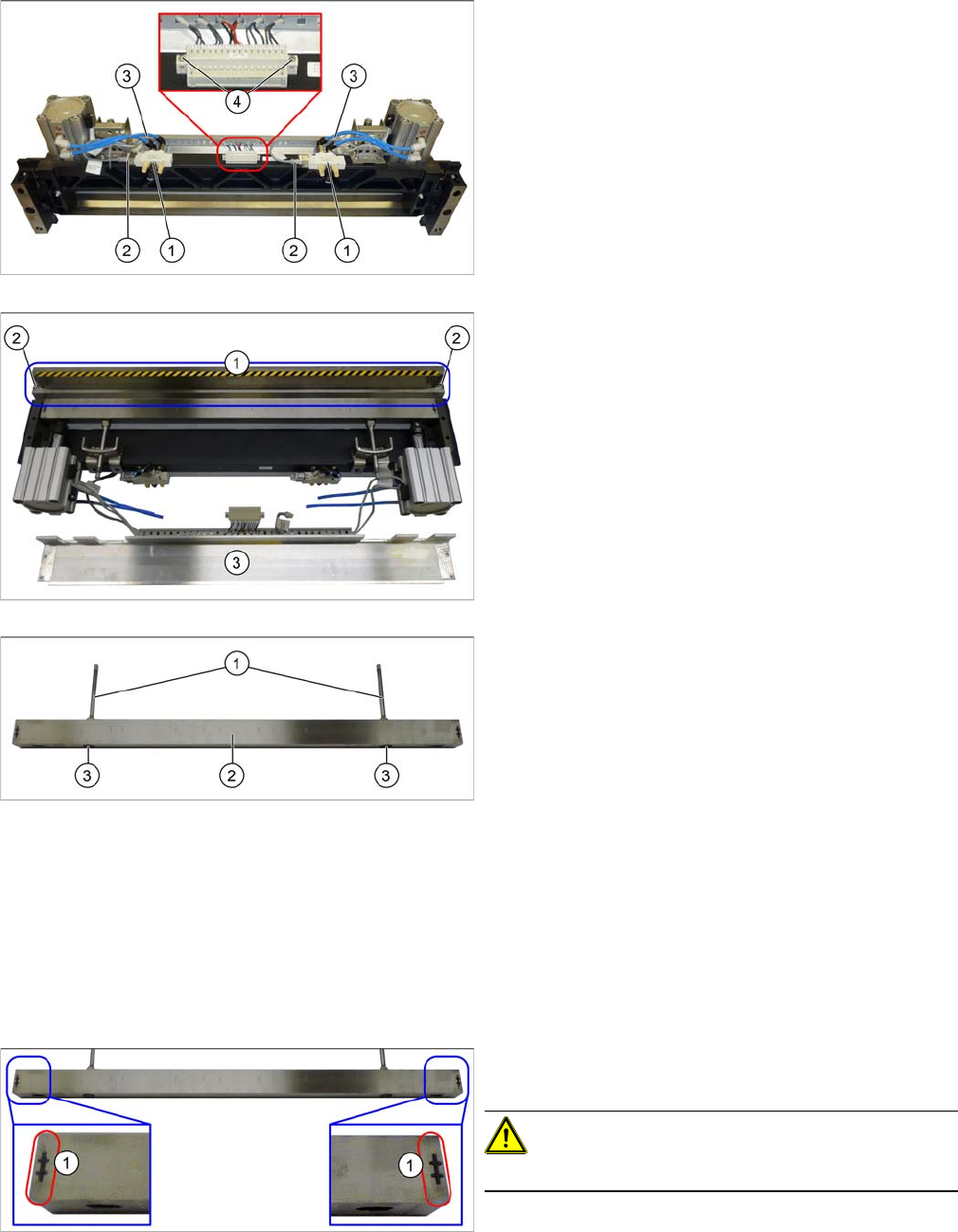
► Remove the locked screws (2) on the left and right of
the return rods.
► Remove the plastic stopper, the elastomeric
spring (1) and the washers on both sides.
► Remove the two screws (1) fastening the articulated
joints on the short-stroke cylinders.
The moveable blades have now been de-coupled.
► Check that the return rods (1) can be moved. You
may need to carefully loosen these up with a rubber
mallet.
► Undo the four screws (1) fastening the cover on the
left and right and then remove the two shim
plates (2).
► Remove the two guidances (3) on the left and right
sides.
Service Work Conveyor
3.11.5 Replacing the Cutter Blades Cutter
Service Manual SIPLACE SX1/SX2/DX1/DX2 FS02 237
Installation – preparations
► Clean all parts and the cutter before installation. Observe the following points:
▪ The new blades are covered with a fine lubrication film. Do not use fat dissolving agents on the
blades (risk of rust film forming) or apply any additional lubrication (risk of contamination by particles
sticking to the blades). This would only impair the movement of the moveable blade.
▪ If the new blades are not clean, carefully rub them (wear protective gloves) with a well folded, clean
and dry cloth. Do not use fat dissolving agents!
▪ Before installation, lubricate the sliding surface of the moveable blade.
▪ Clean all metal parts on the left and right of the cutter and the return rods to remove grease and con-
taminants.
▪ If present, any side buffers on the blades must be checked and replaced if necessary.
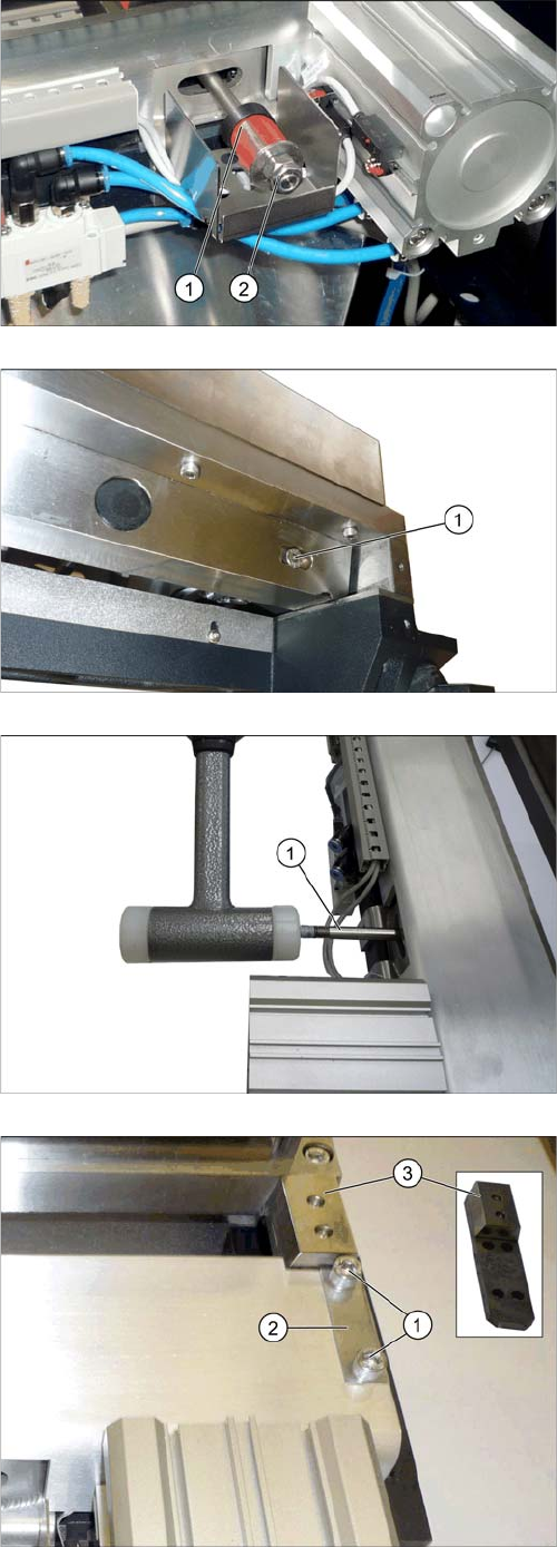
► Unplug the electrical connections (2) from the
valves (1).
► Unplug the pneumatic hoses (3) from the valves.
Mark their positions, to make clear assignment easier
later on.
► Remove the two fastening screws on the terminal
strip.
The terminal strip is now only connected to the cables.
► Swing the top cover (3) forwards.
► Undo the two screws (2) fastening the fixed blade (1)
and then remove the blade.
► Take the moveable blade (2) out of the cutter.
► Remove the covers (3) [03087746-xx] on the fasten-
ings screws.
► Undo the screws (3) fastening the return rods (1) and
then remove the return rods.
▪ Grease the contact and sliding surfaces (1) for the
moveable blade with Klüberplex BEM 34-132.
CAUTION!
Do not grease any other surfaces on the blade.
Service Work Conveyor
Cutter 3.11.5 Replacing the Cutter Blades
238 Service Manual SIPLACE SX1/SX2/DX1/DX2 FS02
Installation
► Insert the moveable blade with the return rods into the cutter.
► Connect the articulated joints of the short-stroke cylinder with the moveable blade. Tighten these
with a torque of 8.8 Nm. Secure the screws with Loctite. Fit the plastic covers on the screws and
knock into place with a rubber mallet.
► Make sure that all metal parts on the left and right of the cutter are clean. Otherwise there is a risk
of head crash!
► Fit the fixed blade onto the cutter. Tighten the screws to a torque of 8.8 Nm. Secure the screws with
Loctite.
► Fit the guidances, the upper cover plate and the shim plates with the four fastening screws on both
sides.
Make sure that all parts are flush against the outer side of the cutter.
Secure the screws with Loctite.
Tighten the screws to a torque of 8.8 Nm.
► Fit the plastic stoppers and elastomeric springs (see "3.11.6 Replacing the Elastomeric Spring
(Blade Damping)" [ ➙ 241]).
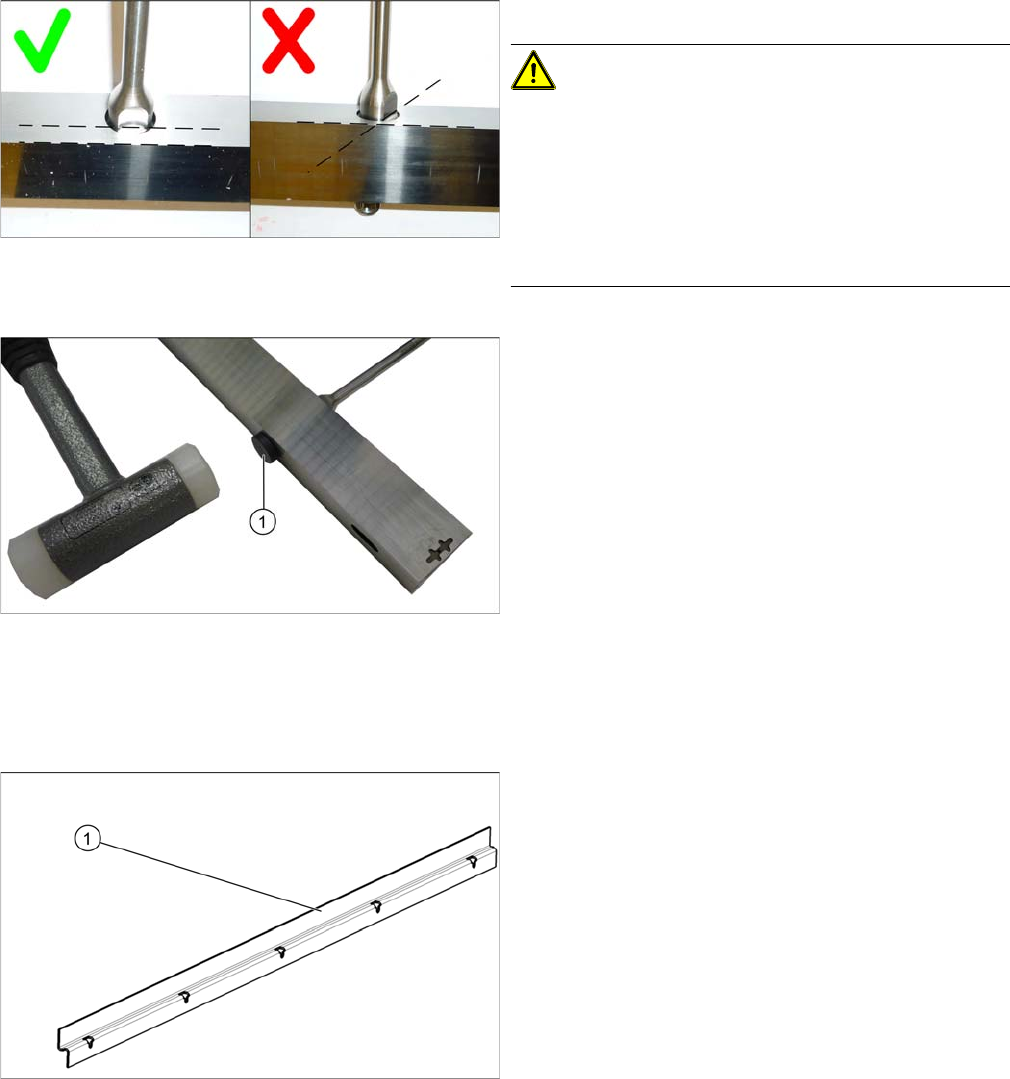
► Fit the return rods onto the moveable blade.
CAUTION!
Secure the screws with Loctite 243.
Make sure that the surfaces for the fork wrench on the re-
turn rods run parallel to the cutting edge of the moveable
blade.
Do not unintentionally turn the blade. When viewed from
the side, the blade must get narrower the further down
you go.
► Insert the two plastic caps (1) onto the fastening
screws for the return rods and knock them into place
with a rubber mallet.
► Remove any excess edges on the plastic caps with a
knife.
► Insert the cover plate, tilted [0309872-xx] (1) with a
gap of 0.4mm +/-0.1mm to the blade.