00196497-07_SM_SXDX12_en.pdf - 第305页
Description of the Circuit Boards 5.1.3 I/O control unit [03116049-xx] Electrics and Control Service Manual SIPLACE SX1/SX2/DX1/DX2 FS02 305 LEDs, Displays 03052315-02 7-segment disp lay H1 [03052315- 02] Display Status …
Description of the Circuit Boards
Electrics and Control 5.1.3 I/O control unit [03116049-xx]
304 Service Manual SIPLACE SX1/SX2/DX1/DX2 FS02
Overview 03052315-02
Settings
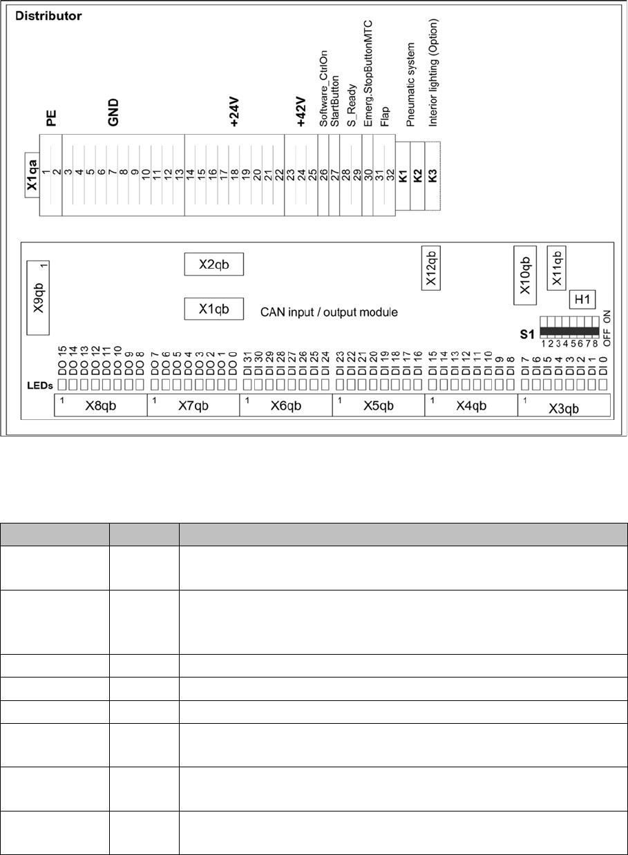
DIP switch block S1 [03052315-02] [03116049-01]
Switch Status Description
S1.1 ON/OFF ON: SX4/DX4, X-Series S
OFF: SX1/SX2, DX1/DX2
S1.2 ON/OFF Ballast resistance
ON: SX1/SX2 from machine no.: N001
OFF: SX4/DX4; X-Series S, SX1/SX2 up to machine no.: Mxxx
S1.3 OFF Reserved
S1.4 OFF Reserved
S1.5 OFF Reserved
S1.6 OFF ON: serial bootstrap mode, make sure that S1.7 must be OFF
OFF: Standard mode
S1.7 OFF ON: CAN bootstrap mode, make sure that S1.6 must be OFF
OFF: Standard mode
S1.8 OFF ON: module in the RESET status
OFF: Standard mode
Description of the Circuit Boards
5.1.3 I/O control unit [03116049-xx] Electrics and Control
Service Manual SIPLACE SX1/SX2/DX1/DX2 FS02 305
LEDs, Displays
03052315-02
7-segment display H1 [03052315-02]
Display Status Description
Dot Flashes Circuit board OK
0 ON Firmware OK
1 ON CAN telegram cannot be transmitted
2 ON FW error: overflow in the CAN bus receiver buffer
3 ON CAN bus controller in the status ERROR PASSIVE
4 ON CAN bus controller in the status BUS OFF
5 ON Processor board received a message instead of a com-
mand
6 ON PowerFail signal active
F ON Other error
Any ON Hardware problem
A ON When initializing: BIOS mode changes to application mode
b ON When booting: head processor remains in BIOS mode
Description of the Circuit Boards
Electrics and Control 5.1.3 I/O control unit [03116049-xx]
306 Service Manual SIPLACE SX1/SX2/DX1/DX2 FS02
03052315-02
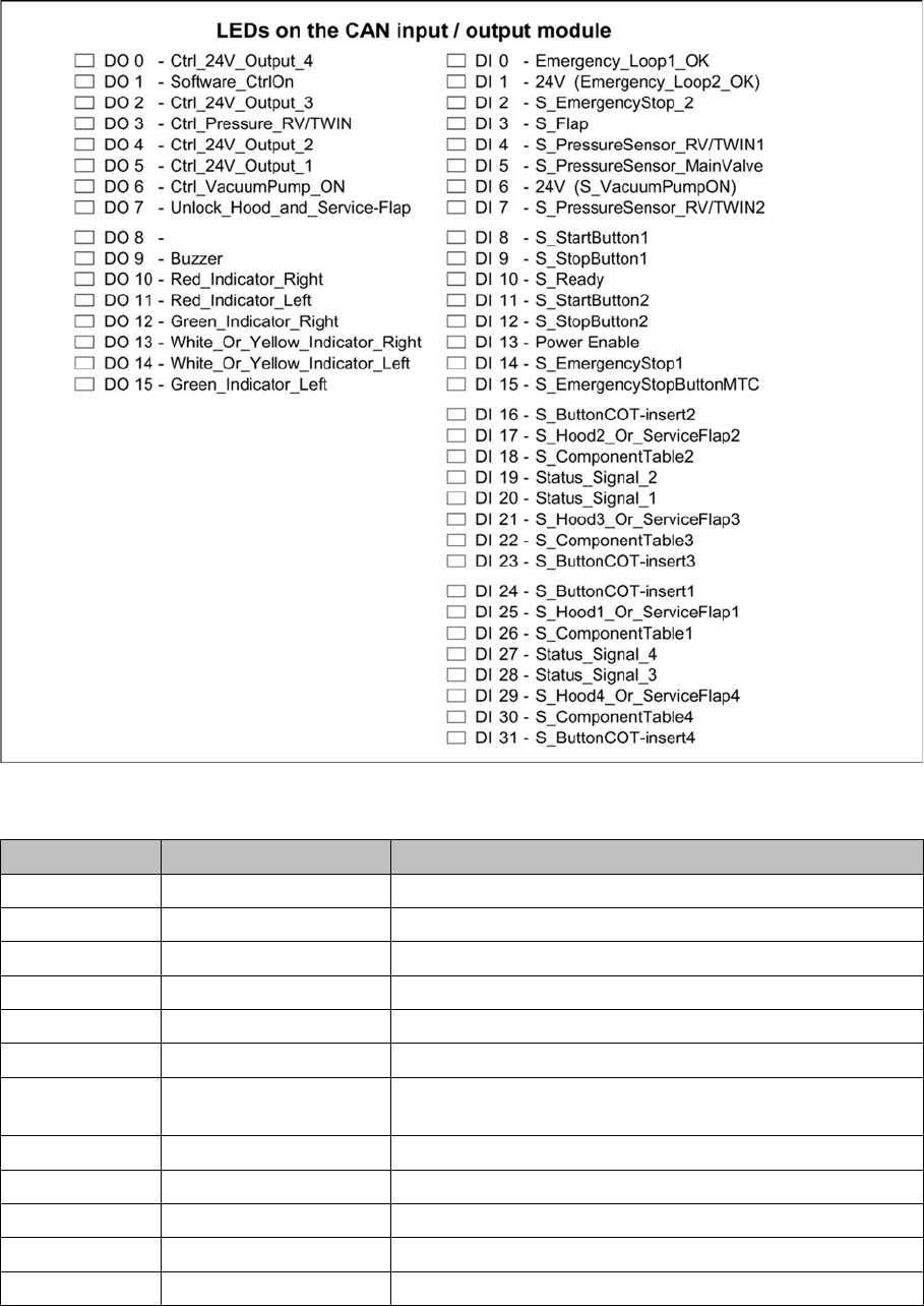
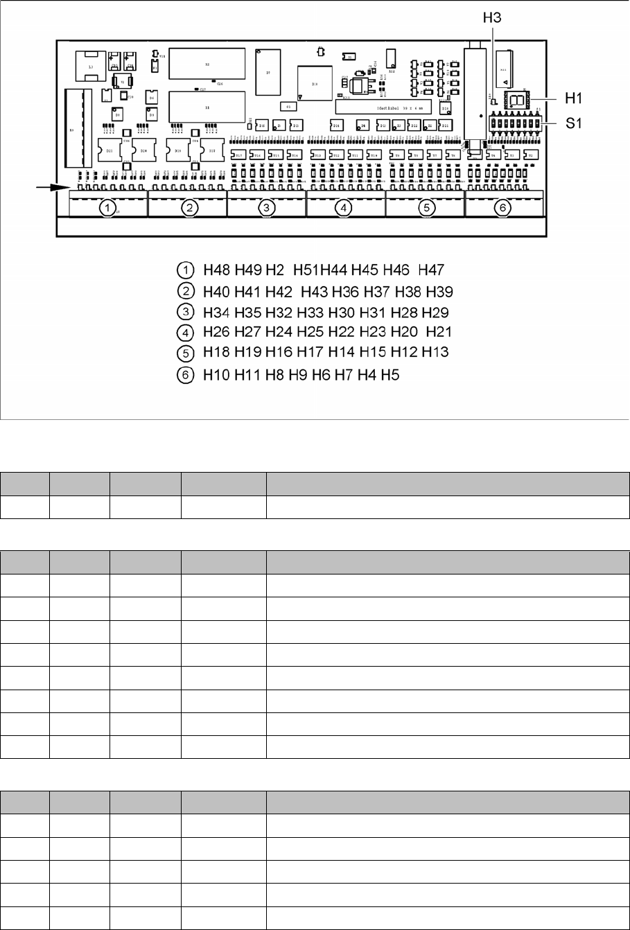
LEDs [03052315-02] [03116049-01]
LEDs Outputs X8qb [03052315-02] [03116049-01]
LEDs Outputs X7qb [03052315-02] [03116049-01]
LED Color Status Signal name Description
H3 RD ON _RSTOUT Signals a RESET
LED Color Status Signal name Description
H48 GN Flashes DO15 No PCB in conveyor lane 2
H49 GN ON DO14 Failure on location 2
H2 GN ON DO13 Failure on location 1
H51 GN Flashes DO12 No PCB in conveyor lane 1
H44 GN ON DO11 Control speaker 2
H45 GN ON DO10 Control speaker 1
H46 GN - DO9 Not used
H47 ON - DO8 24V interlock hood 1 and 2 (option)
LED Color Status Signal name Description
H40 GN - DO7 Not used
H41 GN ON DO6 Vacuum pump switched on (option)
H42 GN OFF DO5 Opens the main valve
H43 GN - DO4 Not used
H36 GN ON DO3 Switches the shut-off valve, COT insert