00196497-07_SM_SXDX12_en.pdf - 第88页
Service Work Conveyor Gantries 3.4.4 Replacing the Gantry Interface X [03065078 - xx] 88 Service Manual SIPLACE SX1/SX2/DX1/DX2 FS02 3.4.4 3 . 4 . 4 R e p la c in g t h e G a n t r y I n t e r f a c e X [ 0 3 0 6 5 0 7 8…
Service Work Conveyor
3.4.3 Replacing the Y Axis Incremental Encoder [03052657-xx] Gantries
Service Manual SIPLACE SX1/SX2/DX1/DX2 FS02 87
Removal
► Switch off the machine, disconnect it from the power supply and secure it to prevent unauthorized
reactivation. Observe the instructions in section "1.2 Preparatory Work..." [ ➙ 13].
Installation
► Follow the removal instructions in reverse order for installation. Also observe the following instruc-
tions:
See also
4.4.3 Checking Track Signals and Zero Pulse [ ➙ 264]
CAUTION
Mounting bracket without end stop edge
There are two versions of the mounting bracket. If you are using a mounting bracket without
end stop edge, please observe the following instructions:
► If you want to refit the same incremental encoder later on (e.g. for cleaning purposes), do
not loosen the mounting bracket!
► If you fit a new incremental encoder, use the mounting bracket provided (with end stop
edge) to simplify installation.
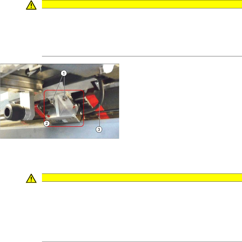
► Mounting bracket without end stop edge (old):
Loosen the two screws (1) fastening the mounting
bracket on the incremental encoder (2).
► Mounting bracket with end stop edge (new):
Where necessary, loosen the two screws fastening
the incremental encoder or mounting bracket.
► Unthread the cable (3) as far as the next connector or
sensor module and then unplug the connector. You
may want to mark the connector positions, to make
clear assignment easier later on. If you need to open
the cable ties, you may want to mark their positions
as well, for easier replacement later on.
CAUTION
Installation instructions
► Clean the reading surface of the incremental encoder with an optical (lint-free) cloth and
ethanol or with a cleansing tip.
► The incremental encoder needs to be fitted at a distance of 0.75 mm parallel to the scale.
Use the plastic foil scale supplied to check this. Make sure that this distance is kept along
the whole width of the incremental encoder and then check the track signals with the track
signal tester.
► If you are using a new mounting bracket, you will need to press the incremental encoder
against the stop edge during installation. This ensures that you achieve parallelism.
Service Work Conveyor
Gantries 3.4.4 Replacing the Gantry Interface X [03065078-xx]
88 Service Manual SIPLACE SX1/SX2/DX1/DX2 FS02
3.4.4
3.4.4 Replacing the Gantry InterfaceX [03065078-xx]
Replacing the Gantry Interface X [03065078-xx]
Parts, equipment and tools
▪ Gantry interface X passive 1 [03065078-xx]
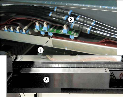
Overview
Removal
► Switch off the machine, disconnect it from the power supply and secure it to prevent unauthorized
reactivation. Observe the instructions in section "1.2 Preparatory Work..." [ ➙ 13].
► Remove the cover above the gantry interface. Depending on the version this is secured with press
studs or screws.
► Loosen the connections on the pneumatic hoses which lead away from the gantry interface.
► Unplug the electrical connections of the Y trailing cable on the top side of the gantry interface.
► Loosen the four screws fastening the gantry interface.
► Unplug the electrical connections on the underside of the gantry interface and remove the interface
from the machine.
1. Gantry interface X (without cover)
2. Pneumatic hoses (without cover)
3. Cover above the gantry interface X
Service Work Conveyor
3.4.4 Replacing the Gantry Interface X [03065078-xx] Gantries
Service Manual SIPLACE SX1/SX2/DX1/DX2 FS02 89
Installation
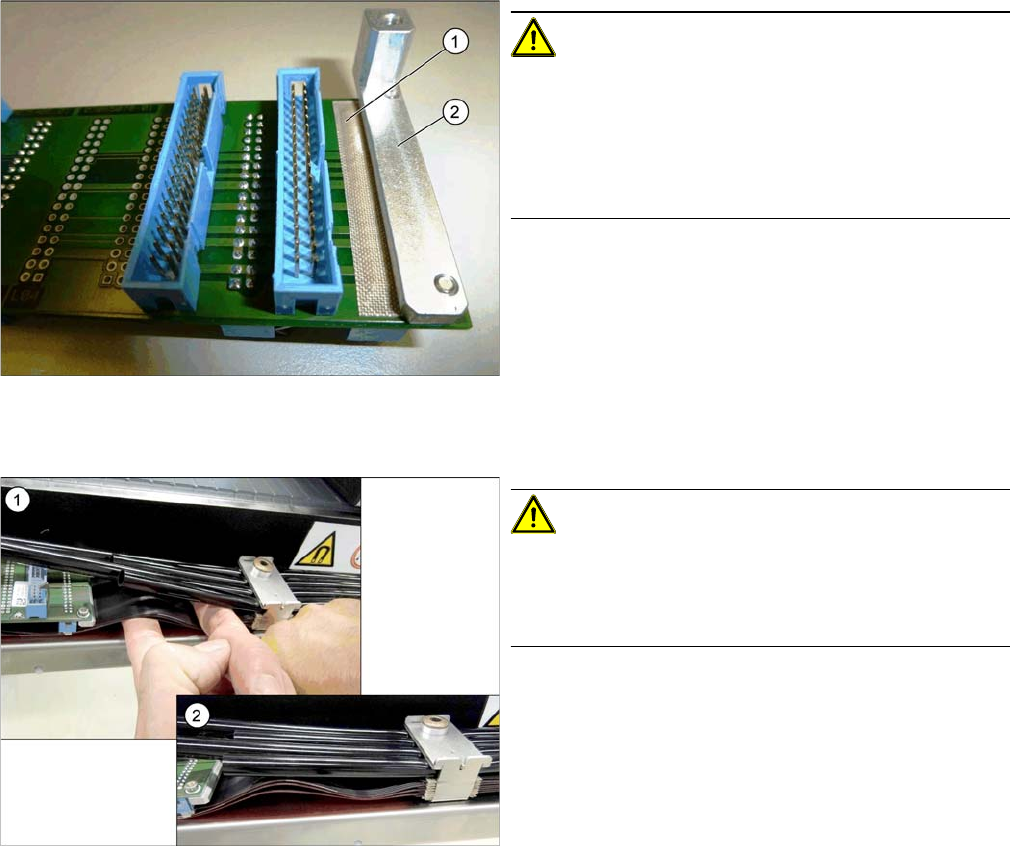
Adhesive Tape for Gantry Interface
► Follow the removal instructions in reverse order for installation. Also observe the following instruc-
tions:
CAUTION!
During assembly, make sure that the connection rail con-
tacts are insulated with adhesive tape (1) in the direction
of the aluminum holder (2). Do not use conductive tape,
recommendation [03000372-xx] "PTFE glass fiber mate-
rial, self-adhesive, width 20mm" for insulating the con-
tacts.
CAUTION!
During installation, lay the flat ribbon cables of the X trail-
ing cable in a slight S shape to prevent the hoses from
pressing against the flat ribbon cables and the connec-
tors.
1. Bend the flat ribbon cable on the trailing interface into
shape
2. Flat ribbon cable on the trailing interface