00196497-07_SM_SXDX12_en.pdf - 第94页
Service Work Conveyor Gantries 3.4.9 Replacing the Vi sion Board Spread Spectrum HCU [0 3067289-xx] 94 Service Manual SIPLACE SX1/SX2/DX1/DX2 FS02 3.4.9 3 . 4 . 9 R e p la c in g t h e V is io n B o a r d S p r e a d S p…
Service Work Conveyor
3.4.8 Replacing the Power Cube Module on the Head Interface Gantries
Service Manual SIPLACE SX1/SX2/DX1/DX2 FS02 93
3.4.8
3.4.8 Replacing the Power Cube Module on the Head Interface
Replacing the Power Cube Module on the Head Interface
Overview
Removal
SXDX12V1V2
► Remove the head interface. Also read section "3.4.7 Replacing the Head Interface [03055072-xx]"
[➙92].
► Remove the four screws fastening the power cube and carefully lift off the power cube from the head
interface.
Installation
► Installation is performed by following the above instructions in the reverse order. Also observe the
following instructions:
See also
3.4.7 Replacing the Head Interface [03055072-xx] [ ➙ 92]
NOTICE
C&P20 P
The following additional conditions must be fulfilled for operating a C&P20 P:
► The MODULE / Powercube must have at least function state [03055514-02].
► You find a complete list of the prerequisites in section Replacing the C&P20 P Head.
MODULE / Powercube [03055514-xx]
NOTICE
Installation instructions
► Make sure that the power cube is positioned correctly.

Service Work Conveyor
Gantries 3.4.9 Replacing the Vision Board Spread Spectrum HCU [03067289-xx]
94 Service Manual SIPLACE SX1/SX2/DX1/DX2 FS02
3.4.9
3.4.9 Replacing the Vision Board Spread Spectrum HCU [03067289-xx]
Replacing the Vision Board Spread Spectrum HCU [03067289-xx]
Parts, Equipment and Tools
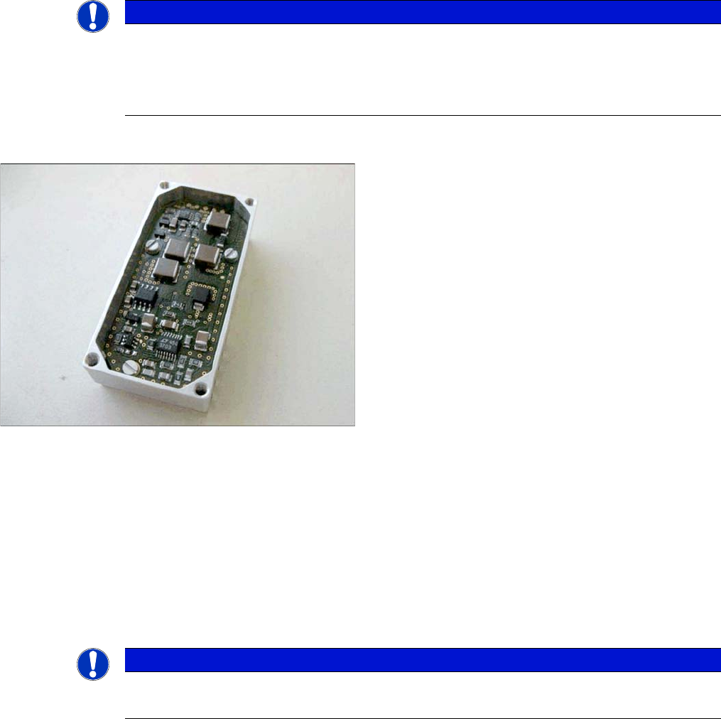
▪ Vision Board Spread Spectrum HCU assembly [03067289-xx]
Overview
Removal
Boards on the Gantry
1. Vision board spread spectrum
2. Head adapter (here the version for the TwinHead with
two HCUs)
3. HCU
4. Head interface
5. Sensor module X
► Switch off the machine, disconnect it from the power
supply and secure it to prevent unauthorized reacti-
vation. Observe the instructions in section "1.2 Pre-
paratory Work..." [ ➙ 13].
► If there is a cover above the boards, dismantle it.
► Open the cable clamps (2) on the two PCB camera
cables (4) and disconnect the cables. You may want
to mark their positions, to make clear assignment
easier later on.
► Disconnect the flat ribbon cable (3).
► Remove the cable tie. (5).
► Undo the five screws (1) fastening the Vision board
spread spectrum and remove the board.
Service Work Conveyor
3.4.10 Replacing the Vision Hotlink Adapter [03050555-xx] Gantries
Service Manual SIPLACE SX1/SX2/DX1/DX2 FS02 95
Installation
► Follow the removal instructions in reverse order for installation. Also observe the following instruc-
tions:
See also
5.2.2 Vision board spread spectrum HCU1 [03067289-xx] [ ➙ 314]
3.4.10
3.4.10 Replacing the Vision Hotlink Adapter [03050555-xx]
Replacing the Vision Hotlink Adapter [03050555-xx]
Parts, equipment and tools
▪ Vision hotlink adapter VHA [03050555-xx]
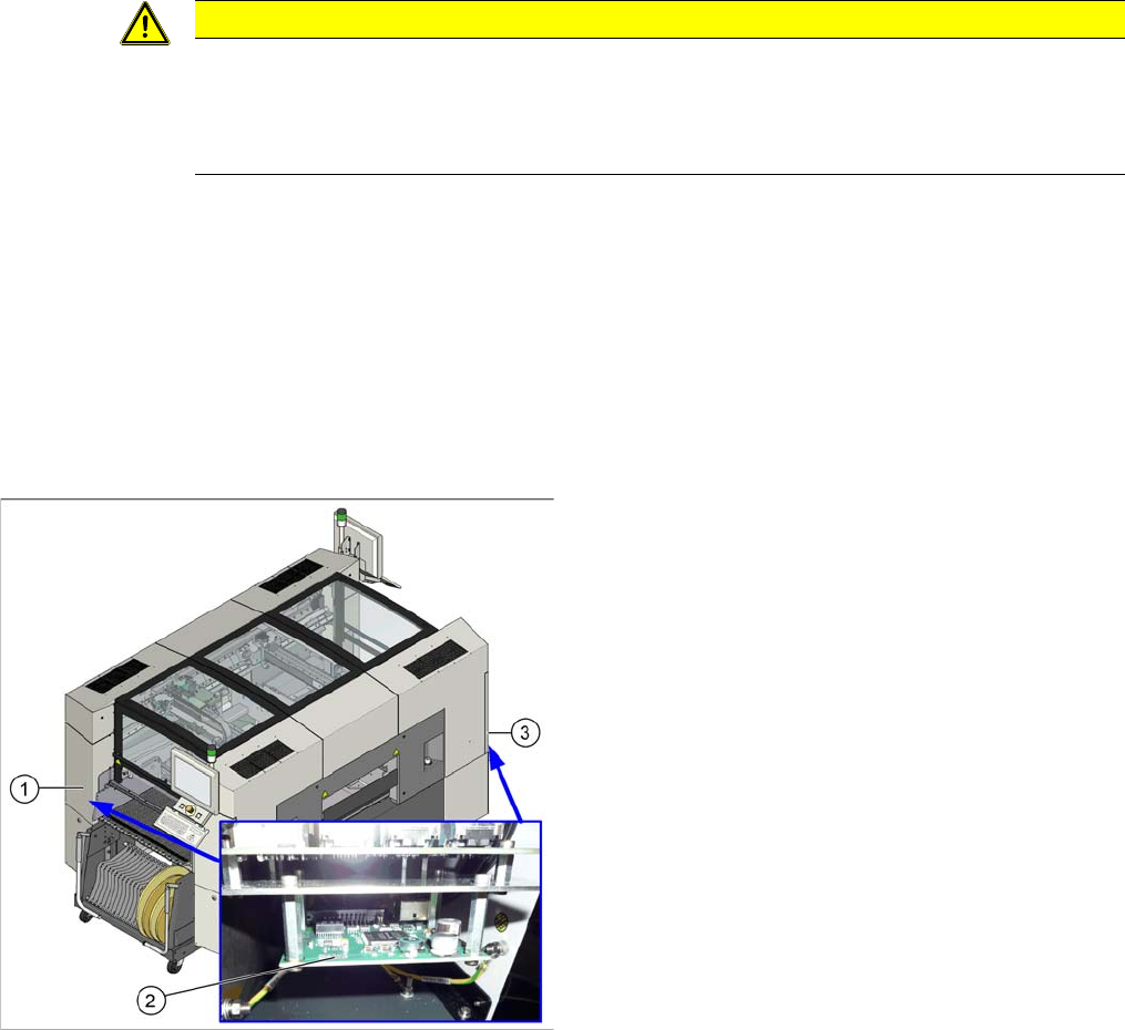
Overview
CAUTION
Installation instructions
► If there is no clamp for the PCB camera cable on the new board, take this off the old board
and fit it on the new one.
► Then perform a firmware update.
1. Sector 1
2. Vision hotlink adapter
3. Sector 3
The Vision hotlink adapter for gantry 1 is located in
sector 1.
The Vision hotlink adapter for gantry 2 (SX 2 only) is lo-
cated in sector 3.