00196497-07_SM_SXDX12_en.pdf - 第280页
Settings Conveyor Settings 4.6.3 Setting the Fixed Conveyor Side 280 Service Manual SIPLACE SX1/SX2/DX1/DX2 FS02 4.6.3 4 . 6 . 3 S e t t in g t h e F ix e d C o n v e y o r S id e Setting the Fixed Conveyor Side 4.6.3.1 …
Settings
4.6.2 Teaching the Sonar Sensor Conveyor Settings
Service Manual SIPLACE SX1/SX2/DX1/DX2 FS02 279
► To teach, press the button on the programming cable for approx. three seconds, until the LED on the
sensor begins to flash.
The switching threshold is set accordingly.
► Remove the setting gauge.
► Loosen the programming cable connections and reconnect the ultrasonic sensor directly to the con-
nection at the machine end.
See also
1.2 Preparatory Work... [ ➙ 13]
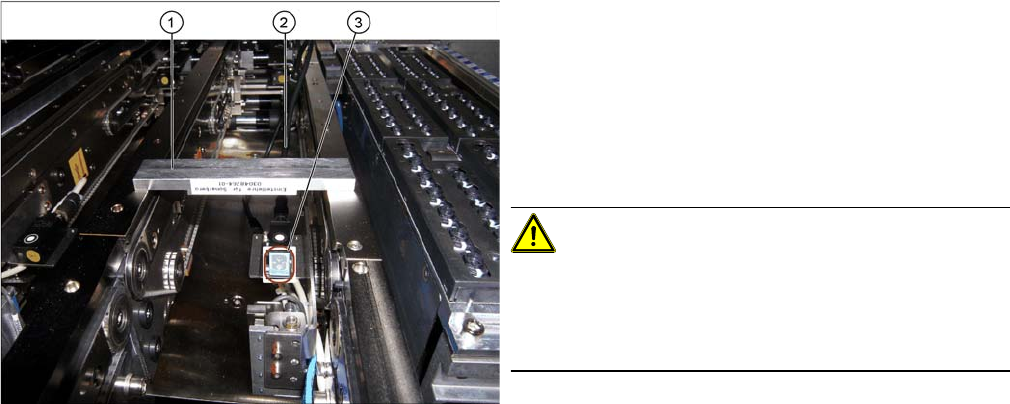
Fitted ultrasonic sensor with programming cable and ad
-
justment gauge (example of X4I shown)
1. Setting gauge
2. Programming cable (fitted)
3. LED on ultrasonic sensor
► The distance to the PCB is defined with the setting
gauge.
Position the setting gauge over the conveyor, so that
it is above the reception area of the ultrasonic sensor.
CAUTION!
Make sure that the gauge is used the right way round.
The gauges can be used for different conveyor types.
Make sure that the gauges are always used the right way
round.
▪ 3mm gap for the X conveyor
▪ 2mm gap for the SX conveyor
Settings
Conveyor Settings 4.6.3 Setting the Fixed Conveyor Side
280 Service Manual SIPLACE SX1/SX2/DX1/DX2 FS02
4.6.3
4.6.3 Setting the Fixed Conveyor Side
Setting the Fixed Conveyor Side
4.6.3.1
4.6.3.1 Setting the Fixed Conveyor Side on Single Conveyors
Setting the Fixed Conveyor Side on Single Conveyors
Parts, equipment and tools
▪ Dowel pin (supplied with conveyor) [03064582-xx]
Overview
Setting
► Use the software to move the flexible conveyor side into the position which allows you best access.
► Switch off the machine, disconnect it from the power supply and secure it to prevent unauthorized
reactivation. Observe the instructions in section "1.2 Preparatory Work..." [ ➙ 13].
► Loosen the fastening screws on both sides of the conveyor.
► Move the conveyor side into the required position.
► Insert the dowel pin and the fastening screw in the new position and tighten the fastening screw.
Perform this step on both sides of the conveyor.
► Remove the dowel pin.
See also
3.6.1 Loosening the Conveyor Side Clamps [ ➙ 143]
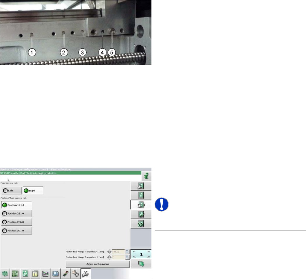
1. Printed circuit board 380 mm
2. Printed circuit board 460 mm (standard)
3. Printed circuit board 508 mm
4. Printed circuit board 560 mm
5. Fastening screw
The dowel pin is inserted at points (1) to (4):
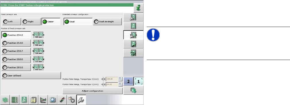
► In the software set the fixed conveyor side and the
position (see "4.6.3.3 Conveyor Sides - Settings"
[ ➙ 282]).
NOTICE!
This menu is accessible from operator level Service (cus-
tomer)!
Settings
4.6.3 Setting the Fixed Conveyor Side Conveyor Settings
Service Manual SIPLACE SX1/SX2/DX1/DX2 FS02 281
4.6.3.2
4.6.3.2 Setting the Fixed Conveyor Side on Dual Conveyors
Setting the Fixed Conveyor Side on Dual Conveyors
The fixed conveyor edge is always set with the software for dual conveyors.
Setting
► In the software set the fixed conveyor side and the
position (see "4.6.3.3 Conveyor Sides - Settings"
[ ➙ 282]).
NOTICE!
This menu is accessible from operator level Service (cus-
tomer)!