00196497-07_SM_SXDX12_en.pdf - 第234页
Service Work Conveyor Cutter 3.11.5 Replacing the Cutter Blades 234 Service Manual SIPLACE SX1/SX2/DX1/DX2 FS02 3.11.5 3 . 1 1 . 5 R e p la c in g t h e C u t t e r B la d e s Replacing the Cutter Blades Parts, Equipment…
Service Work Conveyor
3.11.4 Replacing the Short-Stroke Cylinder [03058693-xx] Cutter
Service Manual SIPLACE SX1/SX2/DX1/DX2 FS02 233
Installation
► Follow the removal instructions in reverse order for installation. Also observe the following instruc-
tions:
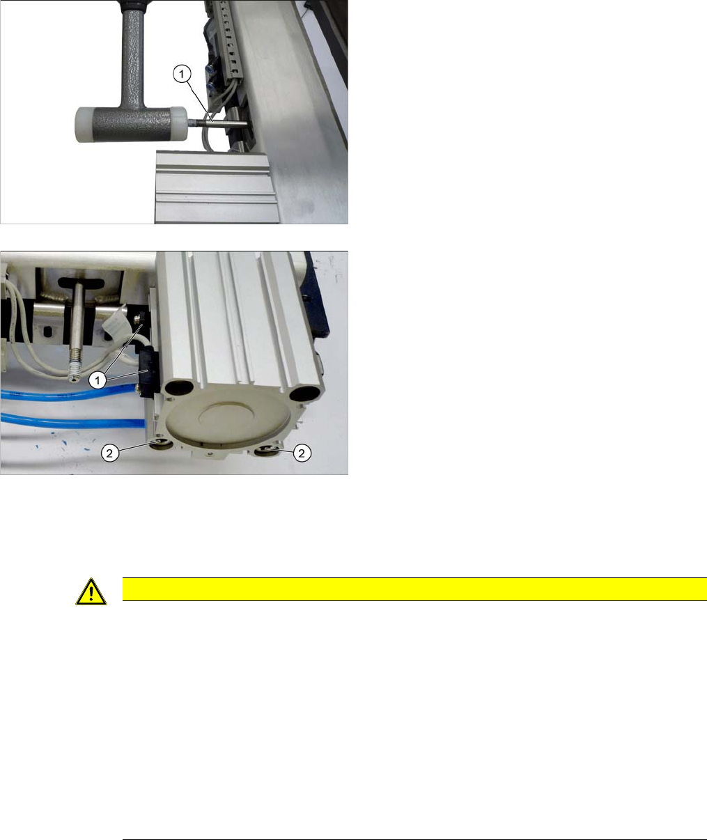
► Check that the return rods (1) can be moved. You
may need to carefully loosen these up with a rubber
mallet.
► Remove the screws fastening the proximity
switch (1). Mark their positions, to make clear assign-
ment easier later on.
► Undo the two screws (2) fastening the short-stroke
cylinder and remove the cylinder.
CAUTION
Installation instructions
► Tighten the fastening screws for the short-stroke cylinder with a torque of 21.4 Nm.
► Set the proximity switch (see "3.11.2 Replacing the Proximity Switch [03061575]" [➙226]).
► The one-way restrictors have been factory set.
Up to SW701.1: Do not change this setting.
From SW701.1: See "4.7.1 Times for Setting the Throttle on the Cutter (From SW707.1)"
[ ➙ 291]).
► Check the distance (gap) of the blades to one another (see also "3.11.5 Replacing the Cut-
ter Blades" [ ➙ 234]).
► Hook the waste tape chute into place. Please also observe section "3.10.10 Replacing the
Waste Tape Chute" [ ➙ 221]. Pay particular attention to the plastic strips and the fuses (if
present).

Service Work Conveyor
Cutter 3.11.5 Replacing the Cutter Blades
234 Service Manual SIPLACE SX1/SX2/DX1/DX2 FS02
3.11.5
3.11.5 Replacing the Cutter Blades
Replacing the Cutter Blades
Parts, Equipment and Tools
▪ SPK blade set for SX1/2 [03093837-xx] with the following contents:
– 1x fixed blade-rail assembly [03058681-xx]
– 1x moveable blade assembly [03065567-xx]
▪ 2x screw cover B series (cover for articulated joint screw) [03080355-xx]
▪ 2x nut cover (cover for the return rod nuts) [03087746-xx]
▪ 2x plastic stopper for cutter SX1/SX2 [03096297-xx]
▪ 2x elastomeric spring 20x8.5x22 (90 Shore A) [03096352-xx]
▪ 4x ISO4032-M8-A2-70 (nuts for return rod and blade) [03008172-xx]
▪ 2x ISO4035–M8-TS [03007684-xx]
▪ 2x articulated joint - B 1/2 [03058685-xx]
▪ 2x DIN6912-M6x35-A2-70 (articulated joint) [03046152-xx]
▪ 2x return rod for movable blade [03086638-xx]
▪Blade
▪ Rubber mallet
▪ Flashlight
▪ Thick protective gloves
▪ Help of second person, if needed
▪ Loctite 243 locking varnish 10 ml [00334892-xx]
▪ Klüber BEM 34-132 lubricant grease, 1 kg tin [00374565-xx]
▪ Interflon Fin grease (spray can) [03020782-xx]
▪ Lubrication nipple DIN71412-A-M6 – straight (tape cutter) [03036936-xx], if required
▪Brush
▪ Open-jawed spanner, size 13
▪ Set of socket keys
▪ Allen key set
▪ Setting gauge for proximity switch buffer [03097370-xx]
▪ Maintenance manual for your machine
CAUTION
Risk of injury!
There is a high risk of injury from the blades and the tape deflector.
► Wear appropriately thick protective gloves!
► Never reach into the cutter from below or into the empty-tape duct from above.
► Make sure that no-one can injure themselves on the cutter after it has been dismantled and
placed next to the machine!
NOTICE
Turn the blade
The fixed and movable blades have been sharpened on both sides. If one side becomes blunt,
you can rotate the blade by 180 degrees to use the other side.
NOTICE
Various greases
This grease is used for a number of purposes, including repeat lubrication of the cutter. The
cutter is initially lubricated at the factory using a different grease (black).
Service Work Conveyor
3.11.5 Replacing the Cutter Blades Cutter
Service Manual SIPLACE SX1/SX2/DX1/DX2 FS02 235
Removal
► Remove the cutter from the machine (see "3.11.1 Replacing the Cutter [03063781Sxx]" [ ➙ 223]).
CAUTION
Risk of injury!
There is a high risk of injury from the blades and the tape deflector.
► Wear appropriately thick protective gloves!
► Never reach into the cutter from below or into the empty-tape duct from above.
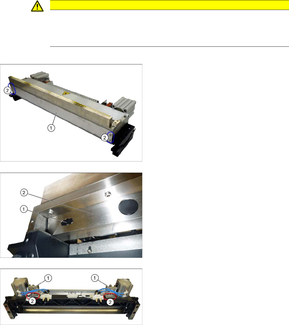
► Undo the four screws (2) fastening the back cover (1)
on the cutter and then remove the cover.
► Remove the two screw covers (1) [03080355-xx] on
the left and right of the moveable blade (2).
► Open the cable ties at the bottom of the protective
plates (1).
► Undo the screws (2) fastening the protective plates
and then remove the protective plates.