00197369-02_AI_PPW_2te_Reihe_X-Serie-S_de_en.pdf - 第102页
Appendix Excerpts from the Service Manual 4 .1.2 Installation Positions of COT Insert and Manual Table (Table Positions) 102 NC Row 2 - NC in Front of MTC 2/WPC PPW 2te Reihe - PPW vor MTC 2/ WPC Setting ► Set the correc…
Appendix
4.1.1 Jumpers on the Nozzle Changer Excerpts from the Service Manual
NC Row 2 - NC in Front of MTC 2/WPC PPW 2te Reihe - PPW vor MTC 2/WPC 101
4
4 Appendix
Appendix
4.1
4.1 Excerpts from the Service Manual
Excerpts from the Service Manual
The following chapters are excerpts from the service manual. For more information, refer to the full ser-
vice manual for your machine.
4.1.1
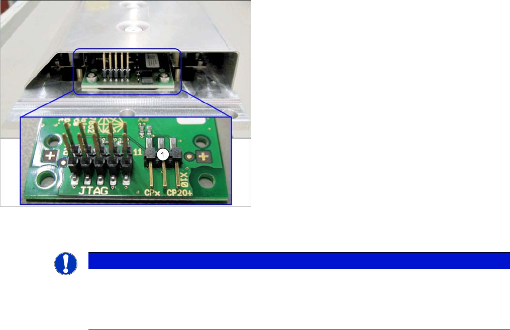
4.1.1 Jumpers on the Nozzle Changer
Jumpers on the Nozzle Changer
The jumper X10 needs to be set at the following nozzle changers:
▪ Nozzle changer basic structure CPx/all assembly - short [03103649-xx]
▪ Nozzle changer basic structure CPx/all assembly - long [03103514-xx]
Overview
Preparation
1. Jumper X10
NOTICE
Before installation
Due to the design, this setting must be performed before installation in the machine.
► If the new nozzle changer is being fitted as a spare part in a machine with I/O module con-
trol, you will need to reconnect the jumper to pin 1-2.
Appendix
Excerpts from the Service Manual 4.1.2 Installation Positions of COT Insert and Manual Table (Table Positions)
102 NC Row 2 - NC in Front of MTC 2/WPC PPW 2te Reihe - PPW vor MTC 2/WPC
Setting
► Set the correct value on the jumper for your head type, software and control method.
Nozzle Changer CP20P - Jumper X10
Jumper X10
4.1.2
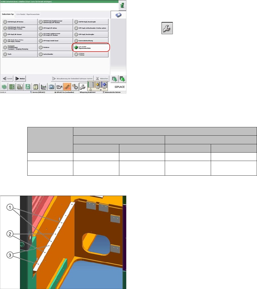
4.1.2 Installation Positions of COT Insert and Manual Table (Table Positions)
Installation Positions of COT Insert and Manual Table (Table Positions)
To check whether the machine has I/O module control,
proceed as follows:
► Switch over to the operator level Service.
► Select the button.
► Select the button Embedded Software.
► Select the button Update Subsystem.
► If I/O module control is present, you will see the entry
Nozzle Changer at I/O Module.
Head Jumper position
SW <= 706.x SW >= 707.x
I/O controller XFCU I/O controller XFCU
CPx, DLM 1-2 1-2 1-2 2-3
C&P20 P --- --- --- 2-3 (factory set-
tings)
The following installation positions apply to the X series
S:
1. Installation position 1
COT insert: X4i S
2. Installation position 2
COT insert, manual table: X4i S
3. Installation position 3
COT insert, manual table: X2 S, X3 S, X4 S
acpage