00197369-02_AI_PPW_2te_Reihe_X-Serie-S_de_en.pdf - 第64页
Brief Description Tools and Equipment Required 2.4.3 Materials for Head-Specific Parts 64 NC Row 2 - NC in Front of MTC 2/WPC PPW 2te R eihe - PPW vor MTC 2/WPC 2.4.3 2 . 4 . 3 M a t e r ia ls f o r H e a d - S p e c if …

Brief Description
2.4.1 Materials for X4i S Product Description
NC Row 2 - NC in Front of MTC 2/WPC PPW 2te Reihe - PPW vor MTC 2/WPC 63
2
2 Brief Description
Brief Description
The relevant upgrade kit extends SIPLACE X-Series S machines by a second row of nozzle changers
for CPP and C&P20 heads as well as TwinHeads.
Machines of types SIPLACE X3 S and X4 S that are equipped with an MTC already have a row of nozzle
changers in front of the MTC.
If these machine types are upgraded with an MTC or WPC later on, the row of nozzle changers has to
be installed as described in this manual.
2.1
2.1 Product Description
Product Description
The second row of nozzle changers extends the relevant machine by an additional four nozzle maga-
zines, thereby increasing its flexibility.
2.2
2.2 Requirements
Requirements
When installing a second row of nozzle changers on machines of type X4i S, the COT insert at the rel-
evant location must be in position 2.
2.3
2.3 Restrictions
Restrictions
Due to longer travel paths, the use of a second row of nozzle changers reduces the placement perfor-
mance.
2.4
2.4 Scope of Delivery
Scope of Delivery
2.4.1
2.4.1 Materials for X4i S
Materials for X4i S
The following parts are needed for each location:
▪ Once for location 2 or 4:
Support option ASP speed flex for row 2 [03090225-xx]
▪ Once for location 1 or 3:
Support option ASP speed flex for row 2 SP1/3 [03097749-xx]
▪ Once per location:
Protective cap assy. [03085665-xx]
▪ Once for location 1 or 3:
Short cover on right [03086067-xx]
▪ Once for location 2 or 4:
Short cover on left [03086070-xx]
▪ Coding sheet box assy. [03084178-xx]
2.4.2
2.4.2 Material for X4 S, X3 S, X2 S
Material for X4 S, X3 S, X2 S
The following parts are needed for each location:
▪ Basic assembly NC row 2/W5 magazine [03089888-xx]
▪ Coding sheet box assy. [03084178-xx]
NOTICE
Outer table position
The COT insert must always be in the outer position.
► In X4i S machines, the COT insert must be moved to the outer position.
► In X4 S, X3 S and X2 S machines, the standard position for the COT insert is already the
outer position.

Brief Description
Tools and Equipment Required 2.4.3 Materials for Head-Specific Parts
64 NC Row 2 - NC in Front of MTC 2/WPC PPW 2te Reihe - PPW vor MTC 2/WPC
2.4.3
2.4.3 Materials for Head-Specific Parts
Materials for Head-Specific Parts
The following parts are needed for each location, depending on the head:
For C&P20 A
▪ Nozzle changer basic structure CPx/all assembly - short [03103649-xx]
▪ Magazine assembly C&P20 A [03016831-xx] (contains one magazine)
For CPP
▪ Nozzle changer basic structure CPx/all assembly - short [03103649-xx]
▪ Nozzle magazine type 20xx CPP [03066107-xx] (contains one magazine)
▪ Nozzle magazine type 28xx CPP [03065782-xx] (contains one magazine)
For C&P20 P
▪ Nozzle changer basic structure CPx/all assembly - short [03103649-xx]
▪ Nozzle magazine type 40xx C&P20 P [03101503-xx] (contains one magazine)
For Twin:
▪ Nozzle changer TH SX series (pos. 1) [00519845-xx] (contains the standard magazine configura-
tion)
2.4.4
2.4.4 Materials for MTC and WPC
Materials for MTC and WPC
2.5
2.5 Tools and Equipment Required
Tools and Equipment Required
Tools
▪ Allen key set
▪ Set of open-jawed spanners
▪ Diagonal cutters
▪ Depth measuring gauge 300 mm [03079617-xx]
Tools
▪ Assembly instructions "NC row 2 - NC in front of MTC 2/WPC – SIPLACE X-Series S" [00197369-xx]
(this manual)
2.6
2.6 Required Working Time
Required Working Time
The complete installation procedure for machines of type X4i S, including software settings, takes ap-
prox. 4 hours if all four locations are converted.
The complete installation procedure for machines of type X3 S and X4 S, including software settings,
takes approx. 3 hours if all four locations are converted.
Machine type and location Designation Item number
X3 S and X4 S location 2
with MTC
Holder nozzle changer TwinHead X series with MTC 00119747-xx
Nozzle changer TH SX series (position 1) 00519845-xx
Query reject bin SX4a_TH, CPP, MTC 03090845-xx
X3 S and X4 S location 2
with WPC and CPP
Basic assembly NC row 2 WPC
Contains: NC_short for CPP, 3x magazine type 20,
1x magazine type 28
03113144-xx
X3 S and X4 S location 2
with WPC and Twin
Basic assembly NC row 2 WPC basic assembly 03115109-xx
Nozzle changer TH SX series (position 1) 00519845-xx
Installation
3.1.1 Preparatory Steps X4i S - Installing the NC Row 2
NC Row 2 - NC in Front of MTC 2/WPC PPW 2te Reihe - PPW vor MTC 2/WPC 65
3
3 Installation
Installation
Select the right section for your machine:
▪ "3.1 X4i S - Installing the NC Row 2" [ ➙ 65]
▪ "3.2 X3 S / X4 S - Installing the NC Row 2" [ ➙ 83]
3.1
3.1 X4i S - Installing the NC Row 2
X4i S - Installing the NC Row 2
3.1.1
3.1.1 Preparatory Steps
Preparatory Steps
► Move the component trolley out of the machine.
► Switch off the machine, disconnect it from the power supply and secure it to prevent unauthorized
reactivation. Observe the instructions in section "1.2 Preparatory Work..." [ ➙ 58].
► Perform the following modifications to the machine before you fit "nozzle changer row 2":
▪ "3.1.1.1 Adjusting the Hood" [ ➙ 65]
▪ "3.1.1.2 Adjusting the Y Buffer" [ ➙ 67]
▪ "3.1.1.3 Adjusting the Hand Guard" [ ➙ 68]
▪ "3.1.1.4 Moving the COT Insert to the Second Table Position" [➙69]
3.1.1.1
3.1.1.1 Adjusting the Hood
Adjusting the Hood
Before the COT insert can be moved to position 2, you need to replace the original protective cover at
the relevant location with the "protective sheet assembly".
Parts required from "protective sheet assembly SX4/DX4" [03085665-xx]
Quantity Designation Item number
1 Protective plate 03081408-xx
1 Track ruler and safety marking 03092020-xx
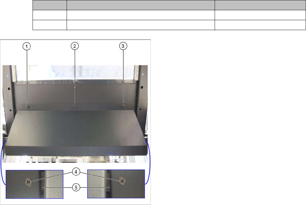
Hood with original protective cover at table position 1
There are three bolts on the inside of the cover (1) to (3),
where the protective cover is hooked up and fixed.
► Remove the three hexagonal nuts that fix the protec-
tive cover and lift off the original cover.
► At (4), remove the fixture sheet on both sides (5).