00197369-02_AI_PPW_2te_Reihe_X-Serie-S_de_en.pdf - 第87页
Installation 3.2.2 Locations 1 to 4 Without M TC X3 S / X4 S - In stalling the NC Row 2 NC Row 2 - NC in Front of MTC 2/WPC PPW 2te Reihe - PPW vor MTC 2/WPC 87 3.2.2.6 3 . 2 . 2 . 6 C o n v e r t in g t h e N o z z le S…
Installation
X3 S / X4 S - Installing the NC Row 2 3.2.2 Locations 1 to 4 Without MTC
86 NC Row 2 - NC in Front of MTC 2/WPC PPW 2te Reihe - PPW vor MTC 2/WPC
3.2.2.5
3.2.2.5 Checking the Height
Checking the Height
After installation, check the height of the basic assembly and of the mount for the nozzle station. You
also need to check the height of the W5 magazine support for configurations with SPS.
► For better access when measuring on the outer side, push the placement head inwards.
► Move the gantry so that the placement head is roughly on the planned nozzle changer position.
Checking the height of the basic assembly and the mount for the nozzle station
Checking the height of the W5 magazine support
NOTICE
Avoid scratching the magnetic strip.
Make sure that the tip of the measuring scale does not touch the magnetic strip, as this might
scratch it!
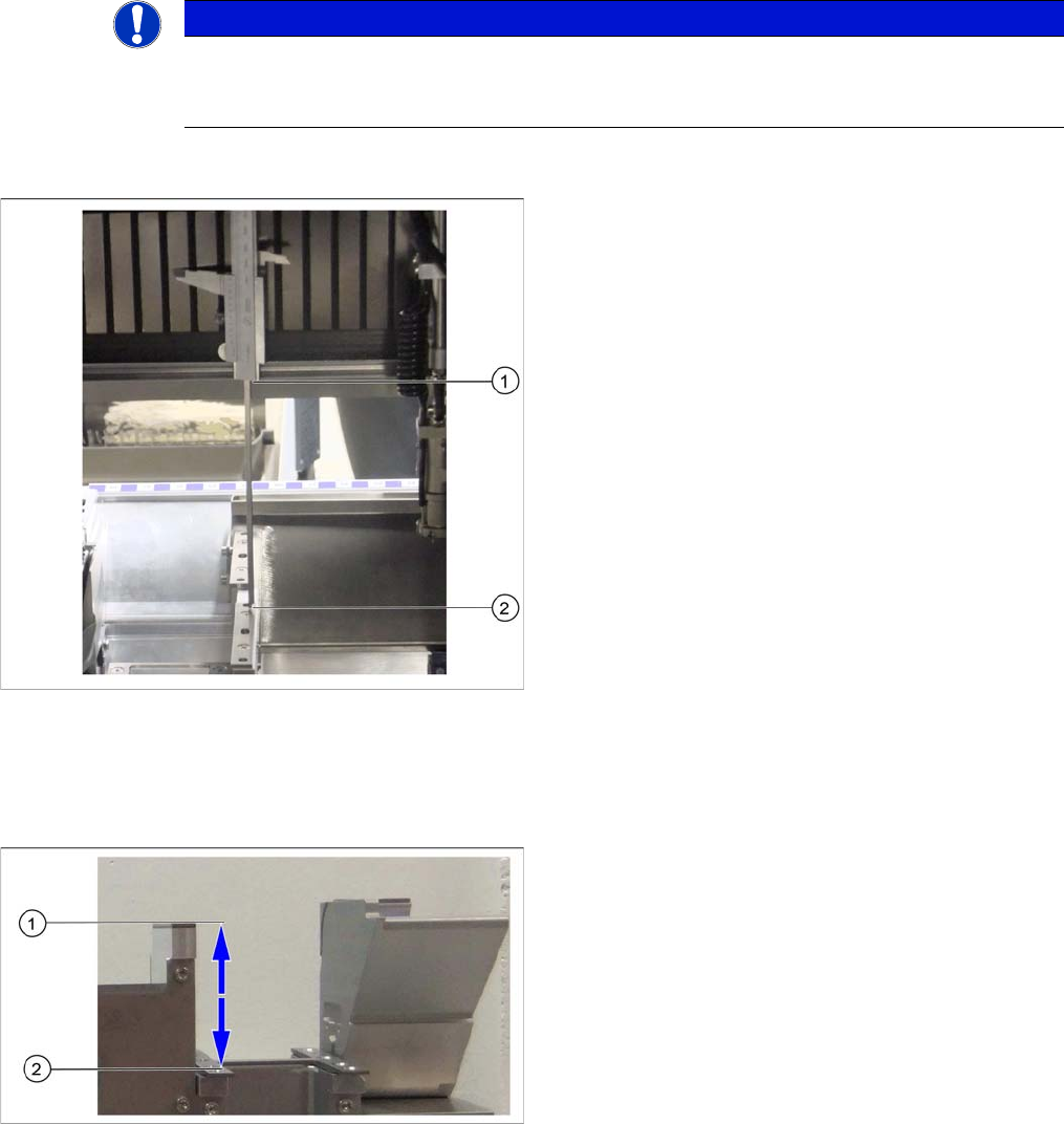
Checking the height (mount for nozzle changer row 2 on
X4i S representing the measuring principle)
► Position the measuring scale vertically onto the top
edge of the X axis lower linear guide at (1) and meas-
ure the distance to the basic assembly contact sur-
face (2) or the mount for the nozzle station.
⇨ The ideal measurement value is 150.0 mm +/- 0.2
mm for the distance to the basic assembly, and
139.0 mm +/- 0.2 mm for the distance to the mount
for the nozzle station.
► If the distance is smaller, you will need to remove the
shim plates from under the contact surfaces and re-
peat the measurement.
Checking the height of the W5 magazine support
If the height of the basic assembly is correctly set to
150.0 mm +/- 0.2 mm, you will need to check the height
of the W5 magazine support.
► Position the measuring scale vertically onto the con-
tact surface of the basic assembly (1) and measure
the distance to the contact surface of the W5 maga-
zine (2).
⇨ The ideal measurement value is 77 mm +/- 0.2
mm.
► If the distance is outside the tolerance range, insert or
remove shim plates as required.
Installation
3.2.2 Locations 1 to 4 Without MTC X3 S / X4 S - Installing the NC Row 2
NC Row 2 - NC in Front of MTC 2/WPC PPW 2te Reihe - PPW vor MTC 2/WPC 87
3.2.2.6
3.2.2.6 Converting the Nozzle Station
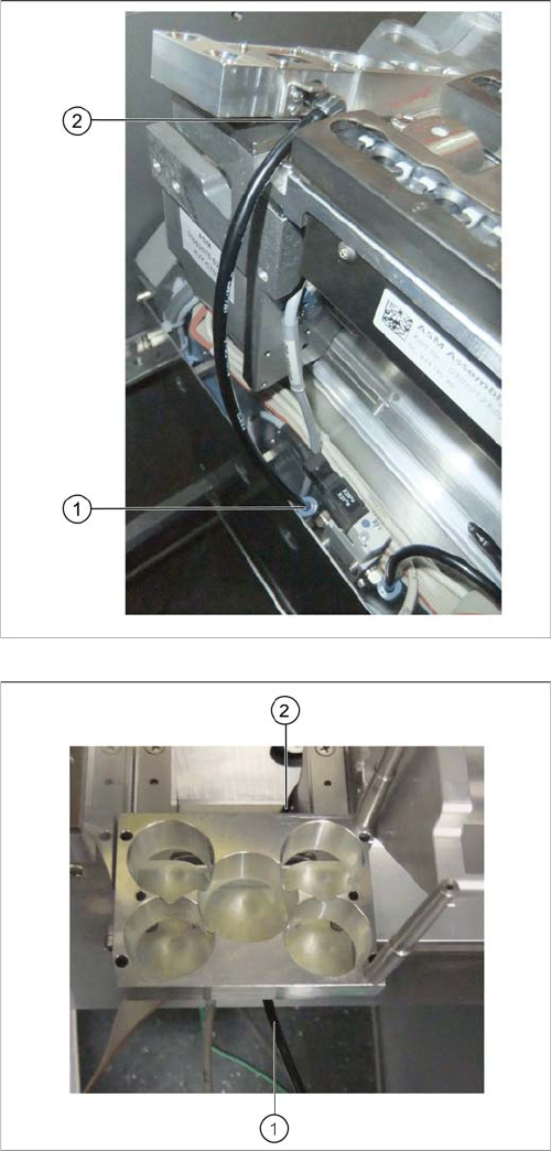
Converting the Nozzle Station
► Unplug the compressed air line from the valve (1) and
the connection at the nozzle station (2).
► Connect the compressed air line from the conversion
kit to the valve (1).
► Remove the reject bin sensor for the first nozzle
changer row.
► Run the compressed air line for the nozzle station un-
der the W5 magazine support (1) and behind the ba-
sic assembly (2).
Installation
X3 S / X4 S - Installing the NC Row 2 3.2.2 Locations 1 to 4 Without MTC
88 NC Row 2 - NC in Front of MTC 2/WPC PPW 2te Reihe - PPW vor MTC 2/WPC
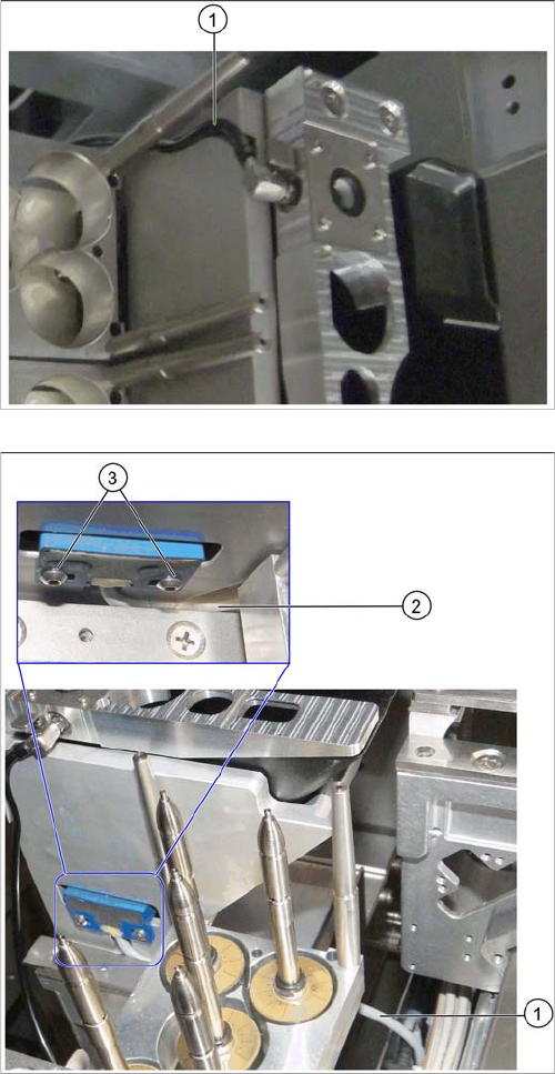
► Insert the nozzle station into the basic assembly.
► Run the compressed air line through the groove on
the basic assembly (1) and connect it to the nozzle
station.
► Insert the reject bin from the first into the second row.
► In the first row, fit the coding sheet into place.
► Run the sensor cable between the W5 magazine sup-
port and the nozzle station container (1) and (2).
Make sure that the cable is not bent or pinched.
► Install the reject bin sensor to the basic assembly for
the second row of nozzle changers and fix it into
place with the screws you removed earlier (3).