00197369-02_AI_PPW_2te_Reihe_X-Serie-S_de_en.pdf - 第79页
Installation 3.1.7 Inserting the NC ASP Support Plate X4i S - In stalling the NC Row 2 NC Row 2 - NC in Front of MTC 2/WPC PPW 2te Reihe - PPW vor MTC 2/WPC 79 Coding sheet The coding s heet ("NO BOX") must eit…
Installation
X4i S - Installing the NC Row 2 3.1.7 Inserting the NC ASP Support Plate
78 NC Row 2 - NC in Front of MTC 2/WPC PPW 2te Reihe - PPW vor MTC 2/WPC
3.1.7
3.1.7 Inserting the NC ASP Support Plate
Inserting the NC ASP Support Plate
For configurations with Smart Pin Support, the H-shaped NC ASP support plate for the second row is
installed between the first row of nozzle changers and the nozzle station, if two W5 magazines are to be
used.
Parts required from "Support option ASP speed flex row 2 SP1/3" [03097749-xx]
Additional requirements:
1x Coding sheet box assembly [03084178-xx]
Installation
Quantity Designation Item number
1 NC ASP support plate for row 2 03090087-xx
4 M4x10 03023262-xx
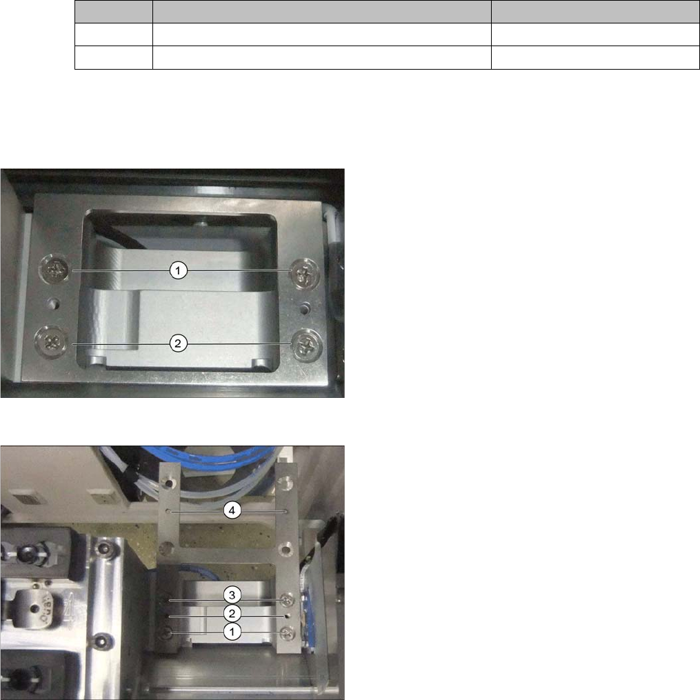
Short support plate
► Remove the short support plate before installing the
H-shaped support plate.
► Remove the screws at (1) and (2).
H-shaped support plate
► Use the four screws to fix the support plate at (1) and
(3).
The points marked (2) and (4) are reserved for fastening
the magazines.
► Fix the magazine for the first nozzle changer row to
(2) and that for row 2 to (4).
Installation
3.1.7 Inserting the NC ASP Support Plate X4i S - Installing the NC Row 2
NC Row 2 - NC in Front of MTC 2/WPC PPW 2te Reihe - PPW vor MTC 2/WPC 79
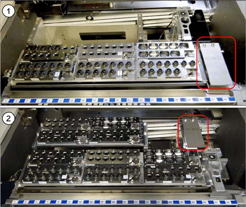
Coding sheet
The coding sheet ("NO BOX") must either be fitted to the
row 1 or row 2 nozzle station, depending on the configu-
ration.
1. With SPS: row 1.
2. Without SPS: row 2
► Fit the coding sheet into place using two screws.
Installation
X4i S - Installing the NC Row 2 3.1.8 Checking the Height
80 NC Row 2 - NC in Front of MTC 2/WPC PPW 2te Reihe - PPW vor MTC 2/WPC
3.1.8
3.1.8 Checking the Height
Checking the Height
After installation, check the height of the second nozzle changer row. You also need to check the height
of the "ASP support plate" for configurations with SPS [03090087-xx].
► For better access when measuring on the outer side, push the placement head inwards.
► Move the gantry so that the placement head is roughly on the planned nozzle changer position.
Checking the height of the second nozzle changer row
Checking the height of the SPS magazine support (ASP)
NOTICE
Avoid scratching the magnetic strip.
Make sure that the tip of the measuring scale does not touch the magnetic strip, as this might
scratch it!
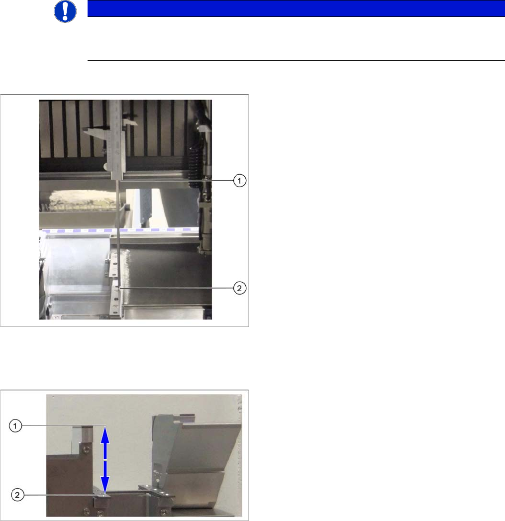
Height check using example of mount for second row
► Check the height of the installed supports or mounts
for the second row.
► Position the measuring scale vertically onto the top
edge of the X axis lower linear guide at (1) and meas-
ure the distance to the support or mount contact sur-
face (2).
⇨ The ideal measurement value is 150.0 mm +/- 0.2
mm.
► If the distance is smaller, you will need to remove the
shim plates from under the contact surfaces and re-
peat the measurement.
Check the height of the SPS magazine support (X3 S/
X4 S representing the measuring principle)
If the height of the second nozzle changer is correctly set
to 150.0 mm +/- 0.2 mm, you will need to check the dis-
tance between the nozzle changer and the ASP support.
► Position the measuring scale vertically onto the con-
tact surface of the nozzle changer (1) and measure
down to the ASP support (2).
⇨ The ideal measurement value is 77 mm +/- 0.2
mm.
► If the distance is outside the tolerance range, insert or
remove shim plates as required.