00197369-02_AI_PPW_2te_Reihe_X-Serie-S_de_en.pdf - 第89页
Installation 3.2.2 Locations 1 to 4 Without M TC X3 S / X4 S - In stalling the NC Row 2 NC Row 2 - NC in Front of MTC 2/WPC PPW 2te Reihe - PPW vor MTC 2/WPC 89 3.2.2.7 3 . 2 . 2 . 7 C o n n e c t in g t h e N C R o w 2 …
Installation
X3 S / X4 S - Installing the NC Row 2 3.2.2 Locations 1 to 4 Without MTC
88 NC Row 2 - NC in Front of MTC 2/WPC PPW 2te Reihe - PPW vor MTC 2/WPC
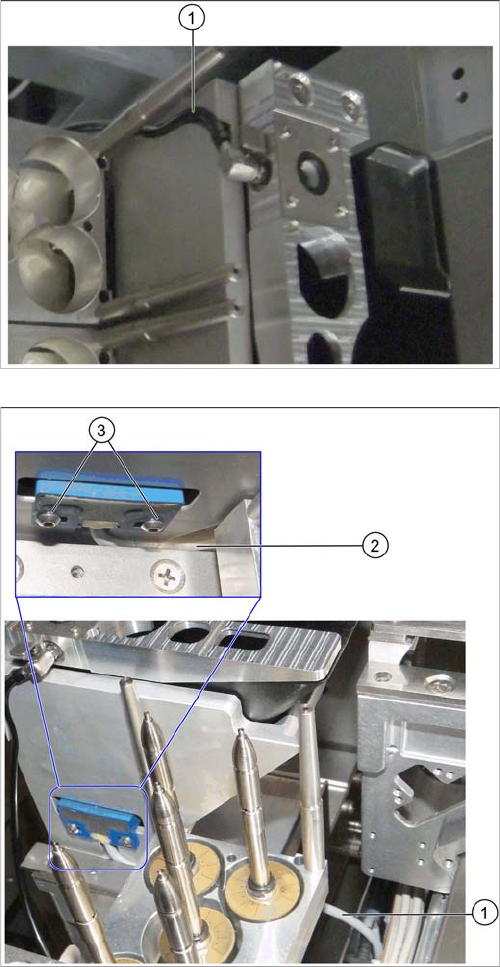
► Insert the nozzle station into the basic assembly.
► Run the compressed air line through the groove on
the basic assembly (1) and connect it to the nozzle
station.
► Insert the reject bin from the first into the second row.
► In the first row, fit the coding sheet into place.
► Run the sensor cable between the W5 magazine sup-
port and the nozzle station container (1) and (2).
Make sure that the cable is not bent or pinched.
► Install the reject bin sensor to the basic assembly for
the second row of nozzle changers and fix it into
place with the screws you removed earlier (3).
Installation
3.2.2 Locations 1 to 4 Without MTC X3 S / X4 S - Installing the NC Row 2
NC Row 2 - NC in Front of MTC 2/WPC PPW 2te Reihe - PPW vor MTC 2/WPC 89
3.2.2.7
3.2.2.7 Connecting the NC Row 2
Connecting the NC Row 2
► Set the jumpers (if present) on the nozzle changers (see "4.1.1 Jumpers on the Nozzle Changer"
[ ➙ 101]).
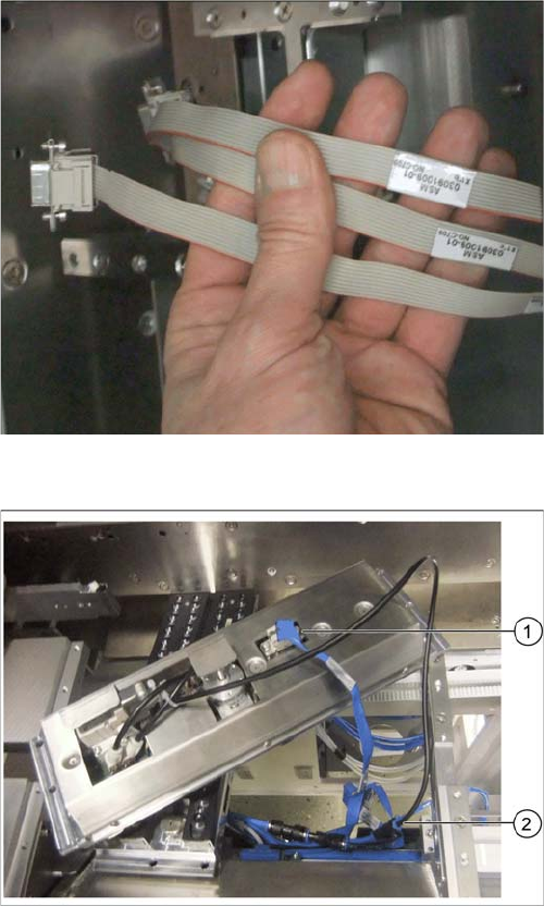
Data cable for NC 2 and SPS
Labeled data cables have been prepared in the machine
for the various configurations of nozzle changers with and
without Smart Pin Support (SPS).
▪ X1*a (NC 1)
▪ X1*b (SPS (1) or NC 2 (without SPS))
▪ X1*c (NC 2 with SPS)
▪ X1*d (SPS2)
Underside of NC 2 with data cable and compressed air
line (example of X4i S)
► Connect the relevant data cable to the underside of
the NC 2 (1).
► Connect the compressed air line to the free connec-
tion on the Y coupling (2).
Installation
X3 S / X4 S - Installing the NC Row 2 3.2.3 Location 2 with MTC
90 NC Row 2 - NC in Front of MTC 2/WPC PPW 2te Reihe - PPW vor MTC 2/WPC
3.2.2.8
3.2.2.8 Inserting and Fixing the NC Rows 1 and 2
Inserting and Fixing the NC Rows 1 and 2
3.2.3
3.2.3 Location 2 with MTC
Location 2 with MTC
3.2.3.1
3.2.3.1 Overview
Overview
Machines of types SIPLACE X3 S and X4 S that are equipped with an MTC already have a row of nozzle
changers in front of the MTC.
If these machine types are upgraded with an MTC later on, the row of nozzle changers has to be installed
as described in this manual.
Parts required
You need the "Nozzle changer holder TwinHead X-Series for MTC" [00119747-xx] and the "Nozzle
changer TH SX-Series (Pos. 1)" [00519845-xx] for these configurations.
Prerequisite
A prerequisite for the installation of the nozzle changer is that an MTC docking unit [03009963-xx] has
already been installed. Observe the relevant installation guide for this.
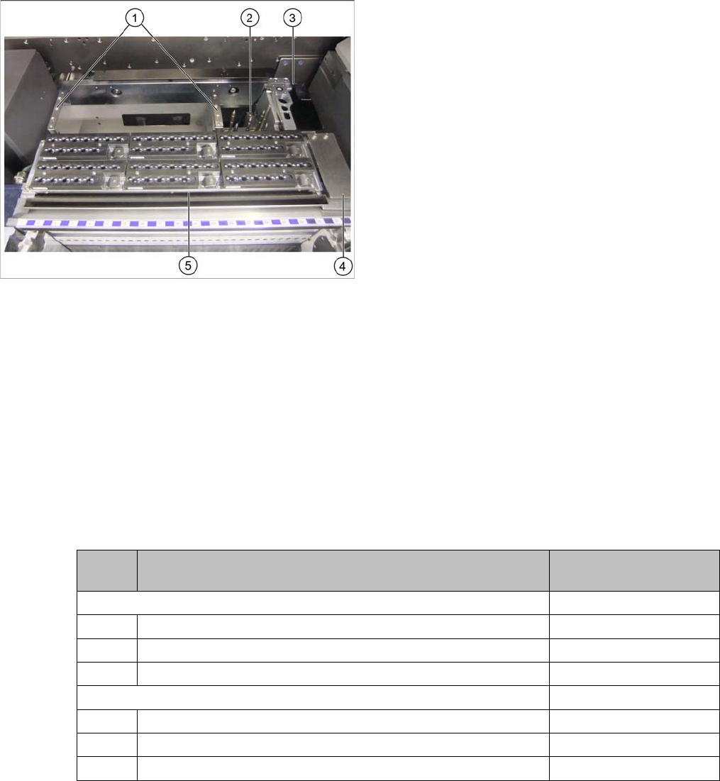
Overall view
1. Basic assembly NC row 2
2. W5 magazine
3. Nozzle station with reject bin inserted
4. Coding sheet
5. NC row 1 with magazine
► Insert the two nozzle changers and screw these to
their mounts.
► Insert the relevant magazine.
⇨ The installation is now complete.
► If you do not want to install another nozzle changer,
continue with section "3.2.5 Final work:" [ ➙ 99].
Quanti-
ty
Designation Item number
Holder nozzle changer TwinHead X-Series with MTC 00119747-xx
1 Holder nozzle changer IC head for X-4 with MTC 03049891-xx
4 DIN912-M5x14-A2-70 03045068- xx
1 Pressure plate 03072884-xx
Nozzle changer TH SX-Series (position 1) 00519845-xx
1 Nozzle changer assembly / TH / B series 03062452-xx
4 ISO 4762 - M5x14-8.8, zinc, TFP 03069114-xx
1 Ass. instruct. Nozzle changer SX-Series 00196578-xx