00197369-02_AI_PPW_2te_Reihe_X-Serie-S_de_en.pdf - 第71页
Installation 3.1.2 Removing the NC Row 1 X4i S - Installing the NC Row 2 NC Row 2 - NC in Front of MTC 2/WPC PPW 2te Reihe - PPW vor MTC 2/WPC 71 Installing the side cover ► Reinstall the side cover. 3.1.2 3 . 1 . 2 R e …
Installation
X4i S - Installing the NC Row 2 3.1.1 Preparatory Steps
70 NC Row 2 - NC in Front of MTC 2/WPC PPW 2te Reihe - PPW vor MTC 2/WPC
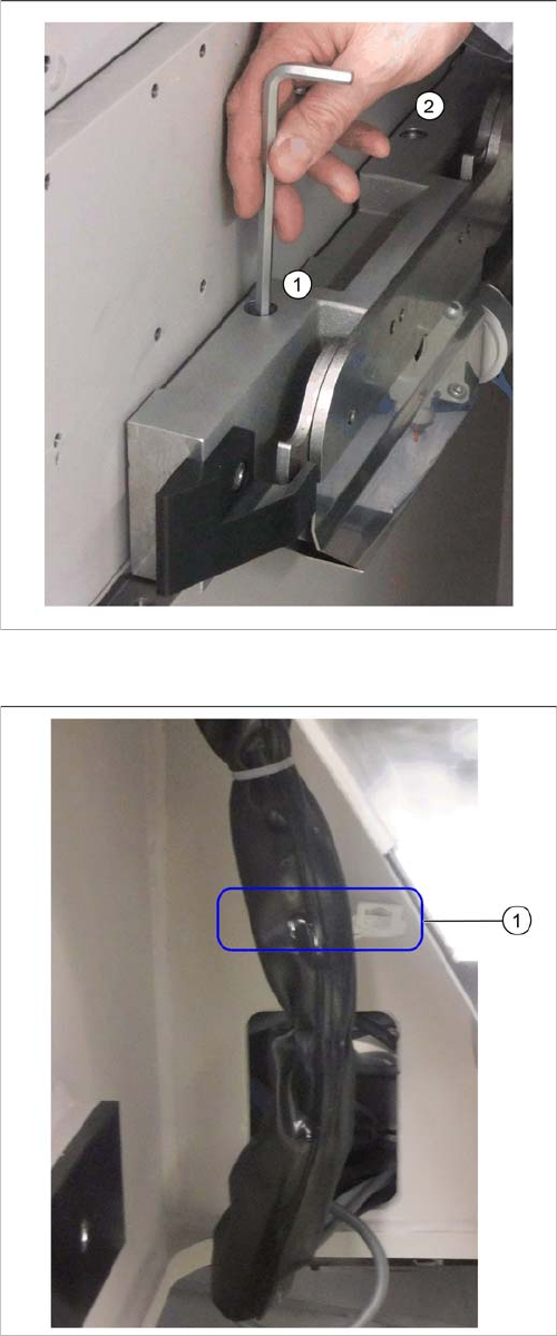
Moving the COT insert
Fastening screws
(1) and (2): Fastening screws on the left of the COT insert
► Remove the two fastening screws on both the left and
the right of the COT insert using an Allen key or a T-
handle.
Fixture point on machine frame
► Remove the cable ties at (1).
Installation
3.1.2 Removing the NC Row 1 X4i S - Installing the NC Row 2
NC Row 2 - NC in Front of MTC 2/WPC PPW 2te Reihe - PPW vor MTC 2/WPC 71
Installing the side cover
► Reinstall the side cover.
3.1.2
3.1.2 Removing the NC Row 1
Removing the NC Row 1
Before you can fit the support and mount for nozzle row 2 and connect the nozzle changer, you need to
remove the nozzle changer in row 1.
► Unplug the connection cable and the compressed air line and then place the nozzle changer to one
side.
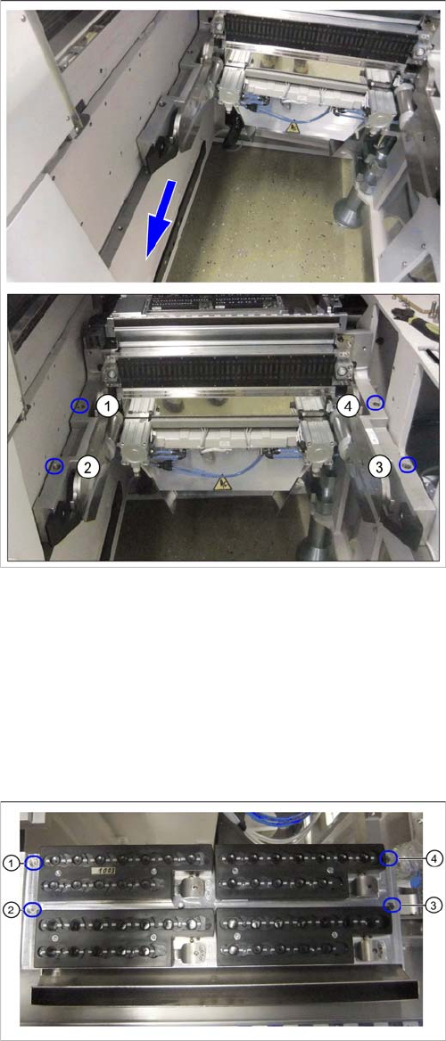
COT insert at second table position
► Pull the COT insert approx. 100 mm forwards to the
second table position.
► Use the four screws (1) to (4) to fasten the COT insert
to its new position.
See also"4.1.2 Installation Positions of COT Insert and
Manual Table (Table Positions)" [ ➙ 102]
Nozzle changer in row 1
► Remove the fastening screws at (1) to (4).
Installation
X4i S - Installing the NC Row 2 3.1.3 Preparing the Compressed Air Connection
72 NC Row 2 - NC in Front of MTC 2/WPC PPW 2te Reihe - PPW vor MTC 2/WPC
3.1.3
3.1.3 Preparing the Compressed Air Connection
Preparing the Compressed Air Connection
To connect the second nozzle changer, you need to branch off the line to the nozzle station.
► Use diagonal cutters to cut the supply line to the nozzle station about 5 cm behind the Y coupling.
3.1.4
3.1.4 Location 1 and 3 – Installing the "Support Option ASP Speed Flex Row 2 SP1/3"
Location 1 and 3 – Installing the "Support Option ASP Speed Flex Row 2 SP1/3"
Parts required from "Support option ASP speed flex row 2" [03090225-xx]
NC option mount
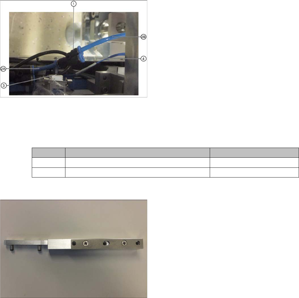
Branched line to nozzle station
1. Y coupling for supplying the nozzle station and NC 2
2. 2A: Original line to nozzle station
2B: Branched line to nozzle station
3. Line to NC 1
4. Connection for line to NC2
► Fit a Y coupling (1) to the original end of the line lead-
ing to the nozzle station (2A).
► Fit the branch end of the line leading to the nozzle
station (2B) into the corresponding connection on the
Y coupling.
► Plug the line leading to NC2 into the connection at (4)
when installing the NC2.
Quantity Designation Item number
2 NC option mount 03005337-xx
2 ISO4762 - M5 x 14-A2-70 03043120-xx
At locations 1 and 3 you need the NC option mount
[03005337-xx] with prefitted shim plates for the left and
right sides.