00197369-02_AI_PPW_2te_Reihe_X-Serie-S_de_en.pdf - 第83页
Installation 3.2.1 Preparatory Steps X3 S / X4 S - Installing the NC Row 2 NC Row 2 - NC in Front of MTC 2/WPC PPW 2te Reihe - PPW vor MTC 2/WPC 83 3.2 3 . 2 X 3 S / X 4 S - I n s t a llin g t h e N C R o w 2 X3 S / X4 S…
Installation
X4i S - Installing the NC Row 2 3.1.10 Inserting and Fixing the NC Rows 1 and 2
82 NC Row 2 - NC in Front of MTC 2/WPC PPW 2te Reihe - PPW vor MTC 2/WPC
3.1.10
3.1.10 Inserting and Fixing the NC Rows 1 and 2
Inserting and Fixing the NC Rows 1 and 2
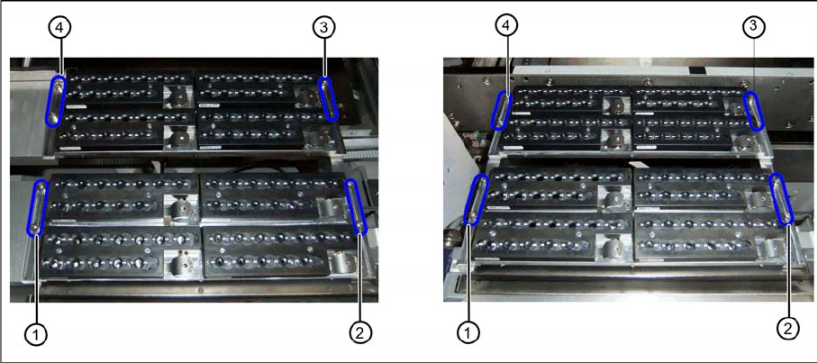
Two nozzle changer rows at location 2 or 4 (left) and location 1 or 3 (right)
► Insert the two nozzle changers and screw these to their mounts.
⇨ NC row 1 at (1) to (2)
⇨ NC row 2 at (3) to (4)
► Insert the relevant magazine.
⇨ The installation is now complete.
If you do not want to install another nozzle changer, continue with the final tasks.
3.1.11
3.1.11 Final Work:
Final Work:
► Push the component trolley back into the relevant location.
► Switch the machine back on and boot the station computer.
► Perform a complete reference run.
► Switch over to the operator level Service.
► Manually configure the second table position in the autoconfiguration.
Table fiducials are measured during job assignment.
► Use the station software to measure the maximum and minimum Y travel path.
► Select either Machine Calibration or Single Calibration and then the nozzle changer calibration.
► Calibrate the magazine position, reject position and pickup heights, one after the other.
► Calibrate the nozzle station and, if present, the SPS magazine(s).
See also
1.2 Preparatory Work... [ ➙ 58]
3.1.11.1
3.1.11.1 Software Settings
Software Settings
► Add the second nozzle changer for the setup in SIPLACE Pro.
Installation
3.2.1 Preparatory Steps X3 S / X4 S - Installing the NC Row 2
NC Row 2 - NC in Front of MTC 2/WPC PPW 2te Reihe - PPW vor MTC 2/WPC 83
3.2
3.2 X3 S / X4 S - Installing the NC Row 2
X3 S / X4 S - Installing the NC Row 2
On machine types X3 S and X4 S, in a configuration without MTC and without TwinHead, the basic as-
sembly of NC row 2/W5 magazine [03089888-xx] is used for installing a second row of nozzle changers
(see "3.2.2 Locations 1 to 4 Without MTC" [ ➙ 83]).
In configurations with MTC and TwinHead at location 2, the nozzle changer TwinHead for MTC X-Series
[00119747-xx] is used (see "3.2.3 Location 2 with MTC" [ ➙ 90]).
In configurations with WPC, another basic assembly may be used, depending on the head type
(see"3.2.4 Location 2 with WPC and Twin/CPP" [ ➙ 92]).
3.2.1
3.2.1 Preparatory Steps
Preparatory Steps
► Switch off the machine, disconnect it from the power supply and secure it to prevent unauthorized
reactivation. Observe the instructions in section "1.2 Preparatory Work..." [ ➙ 58].
► Pull the component trolley out of the machine.
3.2.2
3.2.2 Locations 1 to 4 Without MTC
Locations 1 to 4 Without MTC
See also
3.2.2.3 Preparing the Compressed Air Connection [ ➙ 85]
3.2.2.2 Removing the NC Row 1 [ ➙ 84]
3.2.2.1
3.2.2.1 Overview
Overview
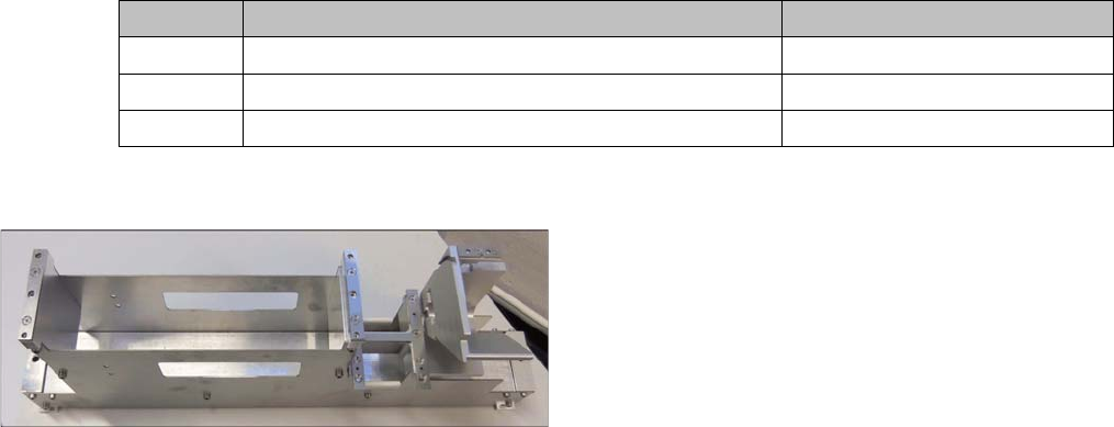
Parts required from the upgrade kit
Basic assembly NC row 2/W5 magazine
Quantity Designation Item number
1 Basic assembly NC row 2/W5 magazine 03089888-xx
2 ISO4762 - M8 x 70-A2-70 03042595-xx
1 Compressed air line for nozzle station
Installation of the basic assembly for the second row of
nozzle changers [03089888-xx] in type X3 S and X4 S
machines is the same for locations 1 to 4 without MTC.
Installation
X3 S / X4 S - Installing the NC Row 2 3.2.2 Locations 1 to 4 Without MTC
84 NC Row 2 - NC in Front of MTC 2/WPC PPW 2te Reihe - PPW vor MTC 2/WPC
Installation position for basic assembly
3.2.2.2
3.2.2.2 Removing the NC Row 1
Removing the NC Row 1
Before you can fit the basic assembly for the nozzle changer row 2 and connect the nozzle changer, you
need to remove the nozzle changer in row 1.
► Unplug the connection cable and the compressed air line and then place the nozzle changer to one
side.
► Expose the connection cables x1*b, x1*c and x1*d.
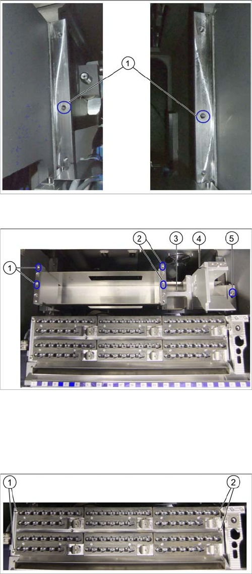
Fixture points on COT insert
The installation place for the basic assembly is behind the
first row of nozzle changers. This basic assembly is fixed
by the middle fixture points on the left and right (1) to the
COT insert support.
Basic assembly in installation position
1. Fixture points for nozzle changer carrier on left
2. Fixture points for nozzle changer carrier on right
3. Support plate for W5 magazine
4. Groove for guiding the compressed air line for the first
row of nozzle changer stations
5. Fixture point for basic assembly on right
Nozzle changer in row 1
► Remove the fastening screws at (1) to (2).