00197369-02_AI_PPW_2te_Reihe_X-Serie-S_de_en.pdf - 第93页
Installation 3.2.4 Location 2 with WPC and Twin/C PP X3 S / X4 S - Installing the NC Row 2 NC Row 2 - NC in Front of MTC 2/WPC PPW 2te Reihe - PPW vor MTC 2/WPC 93 Installation position for basic assembly 3.2.4.2 3 . 2 .…
Installation
X3 S / X4 S - Installing the NC Row 2 3.2.4 Location 2 with WPC and Twin/CPP
92 NC Row 2 - NC in Front of MTC 2/WPC PPW 2te Reihe - PPW vor MTC 2/WPC
3.2.4
3.2.4 Location 2 with WPC and Twin/CPP
Location 2 with WPC and Twin/CPP
See also
3.2.4.2 Removing the NC Row 1 [ ➙ 93]
3.2.4.3 Preparing the Compressed Air Connection [ ➙ 94]
3.2.4 Location 2 with WPC and Twin/CPP [ ➙ 92]
3.2.4.1
3.2.4.1 Overview
Overview
Parts required from the upgrade kit
For Twin:
For CPP:
Basic assembly NC row 2/W5 magazine
CAUTION
Twin and CPP
Observe the different parts lists for Twin and CPP.
Designation Item number
1 Basic assembly NC row 2 WPC basic assembly 03115109-xx
1 Nozzle changer TH SX series (position 1) 00519845-xx
2 ISO4762 - M8 x 70-A2-70 03042595-xx
1 Compressed air line for nozzle station
Quantity Designation Item number
1 Basic assembly NC row 2 WPC
Contains: NC_short for CPP, 3x magazine type 20, 1x magazine
type 28
03113144-xx
2 ISO4762 - M8 x 70-A2-70 03042595-xx
1 Compressed air line for nozzle station
Basic assembly for WPC
NOTICE!
Installation of the basic assembly is the same for Twin
and CPP. Any relevant differences will be mentioned ex-
plicitly.
Installation
3.2.4 Location 2 with WPC and Twin/CPP X3 S / X4 S - Installing the NC Row 2
NC Row 2 - NC in Front of MTC 2/WPC PPW 2te Reihe - PPW vor MTC 2/WPC 93
Installation position for basic assembly
3.2.4.2
3.2.4.2 Removing the NC Row 1
Removing the NC Row 1
Before you can fit the basic assembly for the nozzle changer row 2 and connect the nozzle changer, you
need to remove the nozzle changer in row 1.
► Unplug the connection cable and the compressed air line and then place the nozzle changer to one
side.
► Expose the connection cables x1*b, x1*c and x1*d.
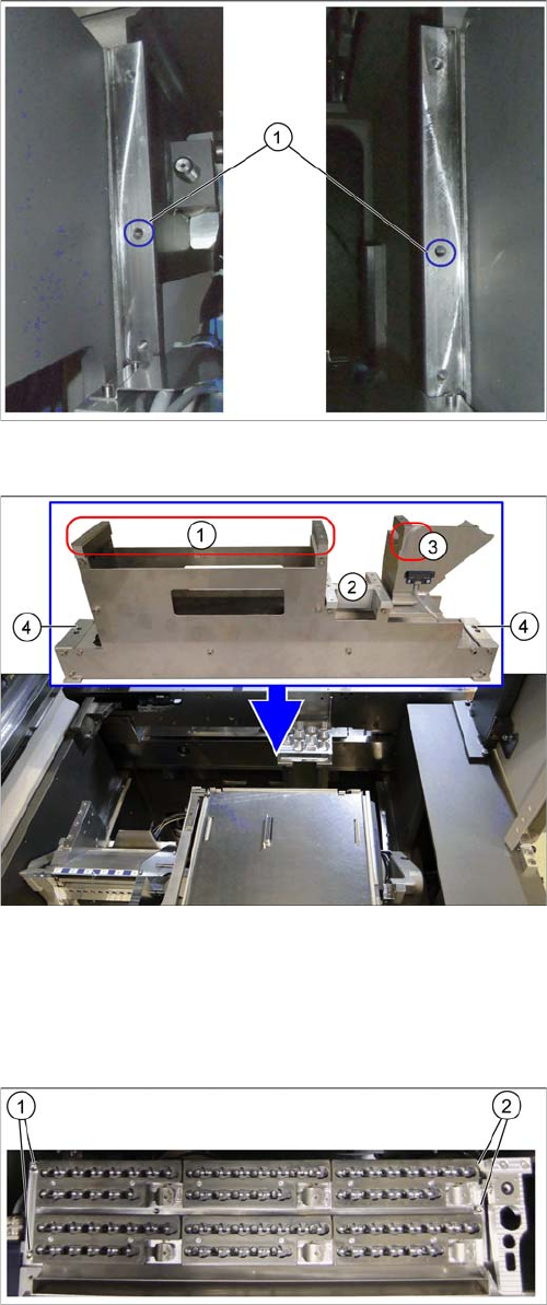
Fixture points on COT insert
The installation place for the basic assembly is behind the
first row of nozzle changers. This basic assembly is fixed
by the middle fixture points on the left and right (1) to the
COT insert support.
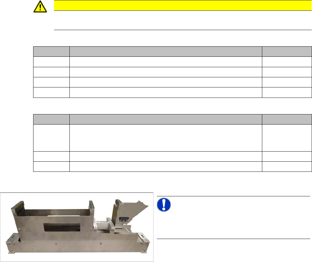
Basic assembly and installation point
1. Installation point for nozzle magazine assembly
2. Support plate for W5 magazine
3. Groove for guiding the compressed air line for the
nozzle changer stations
4. Fixture points for the basic assembly on left and right
Nozzle changer in row 1
► Remove the fastening screws at (1) to (2).
Installation
X3 S / X4 S - Installing the NC Row 2 3.2.4 Location 2 with WPC and Twin/CPP
94 NC Row 2 - NC in Front of MTC 2/WPC PPW 2te Reihe - PPW vor MTC 2/WPC
3.2.4.3
3.2.4.3 Preparing the Compressed Air Connection
Preparing the Compressed Air Connection
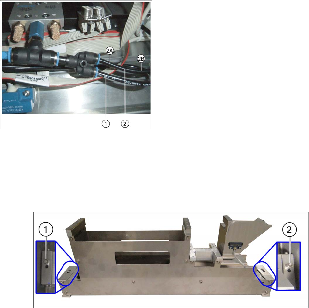
To connect the second nozzle changer, you need to branch off the line to the nozzle station.
► Use diagonal cutters to cut the supply line to the nozzle station about 5 cm behind the Y coupling (2).
► Fit a Y coupling to the original line leading to the nozzle station (2A).
► Fit the branch line leading to the nozzle station (2B) into the corresponding connection on the Y cou-
pling.
► Plug the line leading to NC2 into the remaining connection on the Y coupling when installing the NC2.
3.2.4.4
3.2.4.4 Installing the Basic Assembly
Installing the Basic Assembly
Fixing the basic assembly
► Position the basic assembly at its installation point.
► Use the outer holes on the basic assembly to fix it onto the COT insert support (1) and (2).
Original state of compressed air connection
1. Line to NC 1
2. Cutting point for line to nozzle station
2A: Original line to nozzle station
2B: Branched line to nozzle station