00197369-02_AI_PPW_2te_Reihe_X-Serie-S_de_en.pdf - 第67页
Installation 3.1.1 Preparatory Steps X4i S - Installing the NC Row 2 NC Row 2 - NC in Front of MTC 2/WPC PPW 2te Reihe - PPW vor MTC 2/WPC 67 3.1.1.2 3 . 1 . 1 . 2 A d ju s t in g t h e Y B u f f e r Adjusting the Y Buff…
Installation
X4i S - Installing the NC Row 2 3.1.1 Preparatory Steps
66 NC Row 2 - NC in Front of MTC 2/WPC PPW 2te Reihe - PPW vor MTC 2/WPC
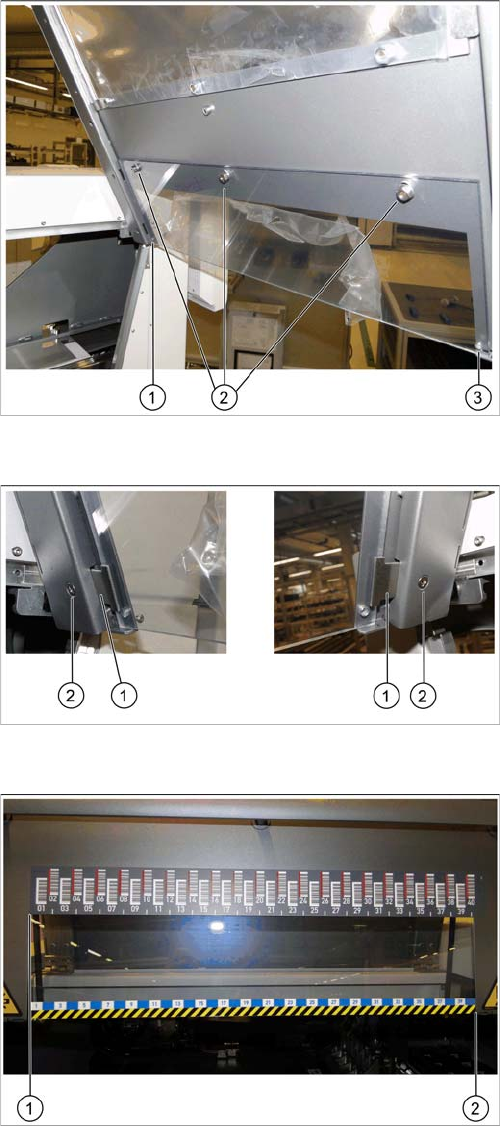
Fixture points for protective plate
► Hook the protective plate onto the three bolts and fas-
ten these into place with the three washers and the
hexagonal nuts (2) that you previously removed.
► Also secure the protective plate with the fixture
sheets on the left (1) and right (3).
Screwing the fixture sheets into place
► Insert the fixture sheets on the left and right (1).
► Screw the fixture plates (2) into place with the screws
that you previously removed.
The barcode ruler must be flat against the disk on the left
of all locations (1).
► Use adhesive to fix the track ruler at all locations to-
wards the machine center (2).
Installation
3.1.1 Preparatory Steps X4i S - Installing the NC Row 2
NC Row 2 - NC in Front of MTC 2/WPC PPW 2te Reihe - PPW vor MTC 2/WPC 67
3.1.1.2
3.1.1.2 Adjusting the Y Buffer
Adjusting the Y Buffer
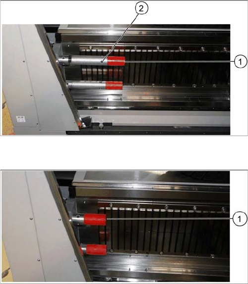
Before the COT insert can be moved to position 2, you need to shorten the length of the Y buffer at the
relevant location.
Length of Y buffer at table position 1
► Unscrew the top red buffer with the help of an Allen
key (1). Pay attention to the bushing.
► Insert the Allen key into one of the auxiliary holes (2)
and remove the middle section of the buffer.
► Repeat these steps for the lower buffer.
Length of Y buffer at table position 2
► Reinsert the red buffer and screw it tight (1).
Installation
X4i S - Installing the NC Row 2 3.1.1 Preparatory Steps
68 NC Row 2 - NC in Front of MTC 2/WPC PPW 2te Reihe - PPW vor MTC 2/WPC
3.1.1.3
3.1.1.3 Adjusting the Hand Guard
Adjusting the Hand Guard
Before the COT insert can be moved to position 2, you need to replace the original hand guard at the
relevant location with the shorter cover on the left and right.
Parts required
Quantity Designation Item number
1 Short cover, right on location 1 and 3 03086067-xx
1 Short cover, left on location 2 and 4 03086070-xx
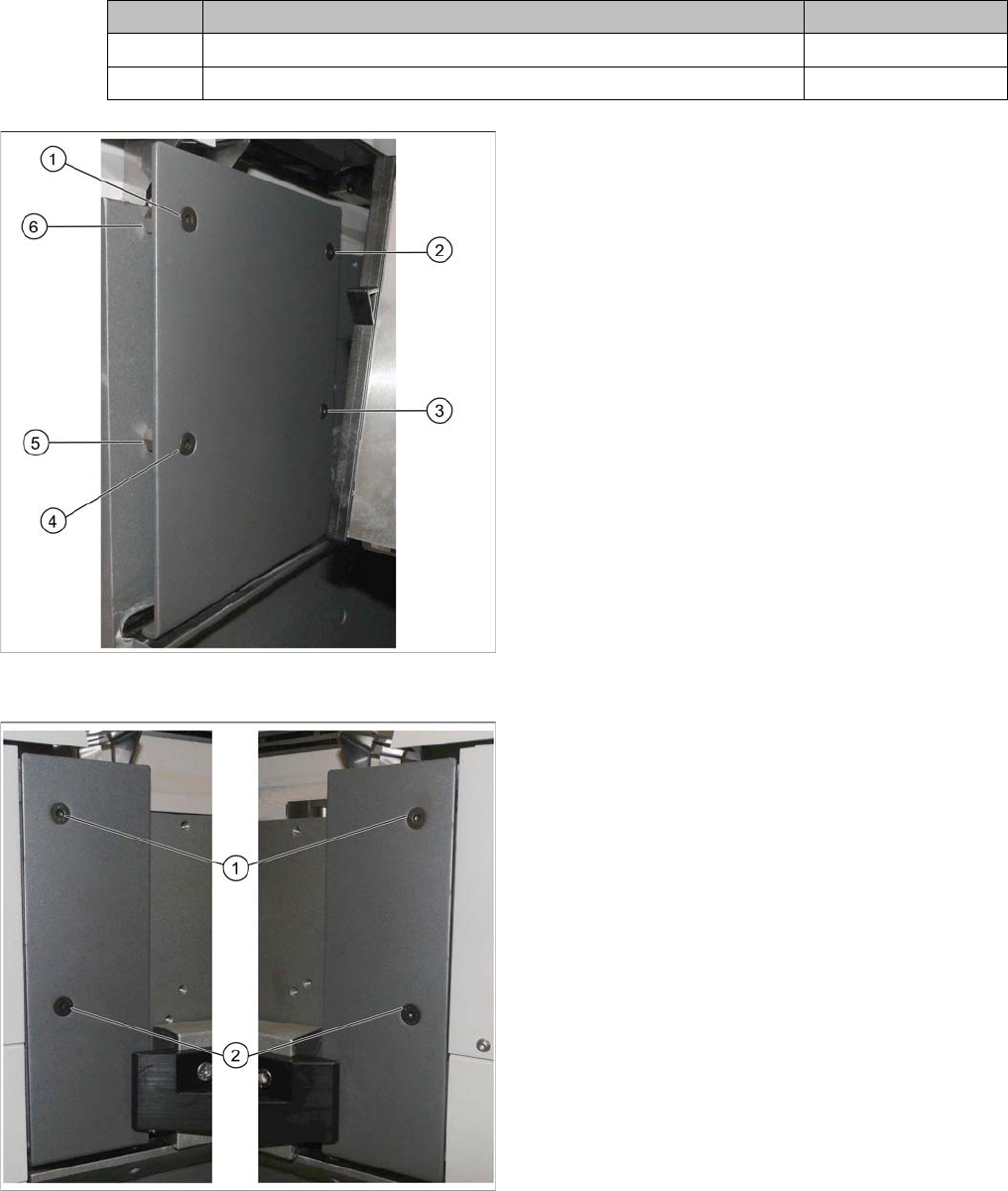
Hand guard on left at table position 1
► Remove the screws at (1) to (4).
► Remove the spacer bolts underneath points (2) and
(3).
The two spacer bolts at (5) and (6) remain.
Short covers on left and right at table position 2
► Insert the short cover:
⇨ Short cover, right on location 1 and 3
⇨ Short cover, left on location 2 and 4
► Use the spacer bolts to screw the cover into place at
(1) and (2).