00197369-02_AI_PPW_2te_Reihe_X-Serie-S_de_en.pdf - 第81页
Installation 3.1.9 Connecting the NC Row 2 X4i S - Installing the NC Row 2 NC Row 2 - NC in Front of MTC 2/WPC PPW 2te Reihe - PPW vor MTC 2/WPC 81 3.1.9 3 . 1 . 9 C o n n e c t in g t h e N C R o w 2 Connecting the NC R…
Installation
X4i S - Installing the NC Row 2 3.1.8 Checking the Height
80 NC Row 2 - NC in Front of MTC 2/WPC PPW 2te Reihe - PPW vor MTC 2/WPC
3.1.8
3.1.8 Checking the Height
Checking the Height
After installation, check the height of the second nozzle changer row. You also need to check the height
of the "ASP support plate" for configurations with SPS [03090087-xx].
► For better access when measuring on the outer side, push the placement head inwards.
► Move the gantry so that the placement head is roughly on the planned nozzle changer position.
Checking the height of the second nozzle changer row
Checking the height of the SPS magazine support (ASP)
NOTICE
Avoid scratching the magnetic strip.
Make sure that the tip of the measuring scale does not touch the magnetic strip, as this might
scratch it!
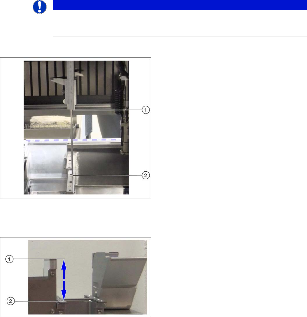
Height check using example of mount for second row
► Check the height of the installed supports or mounts
for the second row.
► Position the measuring scale vertically onto the top
edge of the X axis lower linear guide at (1) and meas-
ure the distance to the support or mount contact sur-
face (2).
⇨ The ideal measurement value is 150.0 mm +/- 0.2
mm.
► If the distance is smaller, you will need to remove the
shim plates from under the contact surfaces and re-
peat the measurement.
Check the height of the SPS magazine support (X3 S/
X4 S representing the measuring principle)
If the height of the second nozzle changer is correctly set
to 150.0 mm +/- 0.2 mm, you will need to check the dis-
tance between the nozzle changer and the ASP support.
► Position the measuring scale vertically onto the con-
tact surface of the nozzle changer (1) and measure
down to the ASP support (2).
⇨ The ideal measurement value is 77 mm +/- 0.2
mm.
► If the distance is outside the tolerance range, insert or
remove shim plates as required.
Installation
3.1.9 Connecting the NC Row 2 X4i S - Installing the NC Row 2
NC Row 2 - NC in Front of MTC 2/WPC PPW 2te Reihe - PPW vor MTC 2/WPC 81
3.1.9
3.1.9 Connecting the NC Row 2
Connecting the NC Row 2
► Set the jumpers (if present) on the nozzle changers (see "4.1.1 Jumpers on the Nozzle Changer"
[ ➙ 101]).
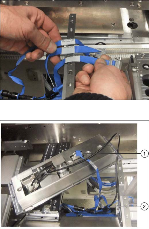
Data cable for NC 2 and SPS
Labeled data cables have been prepared in the machine
for the various configurations of nozzle changers with and
without Smart Pin Support (SPS).
▪ X1*a (NC 1)
▪ x1*b (SPS (1) or NC 2 (without SPS))
▪ X1*c (NC 2 with SPS)
▪ X1*d (SPS2)
Underside of NC 2 with data cable and compressed air
line
► Connect the relevant data cable to the underside of
the NC 2 (1).
► Connect the compressed air line to the free connec-
tion on the Y coupling (2).
Installation
X4i S - Installing the NC Row 2 3.1.10 Inserting and Fixing the NC Rows 1 and 2
82 NC Row 2 - NC in Front of MTC 2/WPC PPW 2te Reihe - PPW vor MTC 2/WPC
3.1.10
3.1.10 Inserting and Fixing the NC Rows 1 and 2
Inserting and Fixing the NC Rows 1 and 2
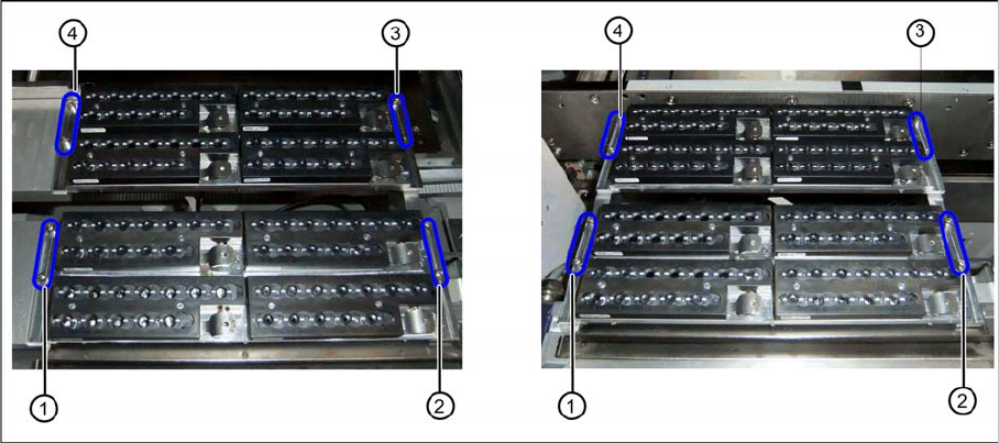
Two nozzle changer rows at location 2 or 4 (left) and location 1 or 3 (right)
► Insert the two nozzle changers and screw these to their mounts.
⇨ NC row 1 at (1) to (2)
⇨ NC row 2 at (3) to (4)
► Insert the relevant magazine.
⇨ The installation is now complete.
If you do not want to install another nozzle changer, continue with the final tasks.
3.1.11
3.1.11 Final Work:
Final Work:
► Push the component trolley back into the relevant location.
► Switch the machine back on and boot the station computer.
► Perform a complete reference run.
► Switch over to the operator level Service.
► Manually configure the second table position in the autoconfiguration.
Table fiducials are measured during job assignment.
► Use the station software to measure the maximum and minimum Y travel path.
► Select either Machine Calibration or Single Calibration and then the nozzle changer calibration.
► Calibrate the magazine position, reject position and pickup heights, one after the other.
► Calibrate the nozzle station and, if present, the SPS magazine(s).
See also
1.2 Preparatory Work... [ ➙ 58]
3.1.11.1
3.1.11.1 Software Settings
Software Settings
► Add the second nozzle changer for the setup in SIPLACE Pro.