00197369-02_AI_PPW_2te_Reihe_X-Serie-S_de_en.pdf - 第97页
Installation 3.2.4 Location 2 with WPC and Twin/C PP X3 S / X4 S - Installing the NC Row 2 NC Row 2 - NC in Front of MTC 2/WPC PPW 2te Reihe - PPW vor MTC 2/WPC 97 ► Insert the nozzle station into t he basic assembly . ►…
Installation
X3 S / X4 S - Installing the NC Row 2 3.2.4 Location 2 with WPC and Twin/CPP
96 NC Row 2 - NC in Front of MTC 2/WPC PPW 2te Reihe - PPW vor MTC 2/WPC
3.2.4.6
3.2.4.6 Converting the Nozzle Station
Converting the Nozzle Station
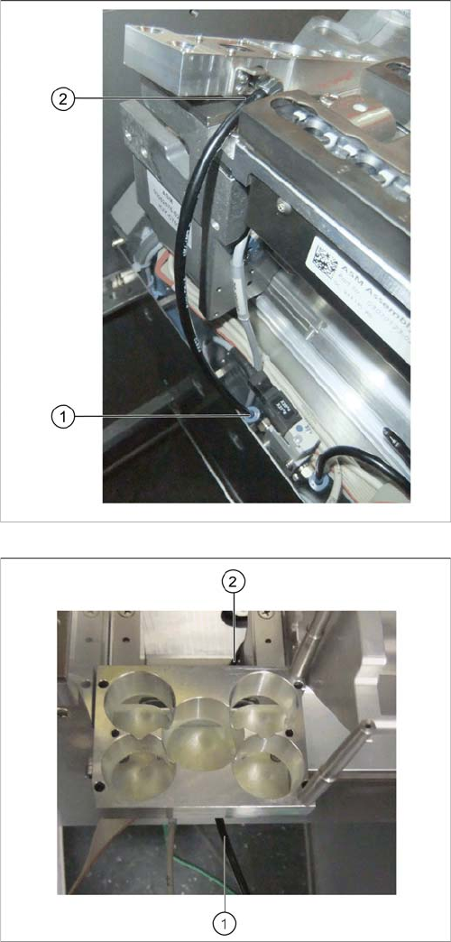
► Unplug the compressed air line from the valve (1) and
the connection at the nozzle station (2).
► Connect the compressed air line from the conversion
kit to the valve (1).
► Remove the reject bin sensor for the first nozzle
changer row.
► Run the compressed air line for the nozzle station un-
der the W5 magazine support (1) and behind the ba-
sic assembly (2).
Installation
3.2.4 Location 2 with WPC and Twin/CPP X3 S / X4 S - Installing the NC Row 2
NC Row 2 - NC in Front of MTC 2/WPC PPW 2te Reihe - PPW vor MTC 2/WPC 97
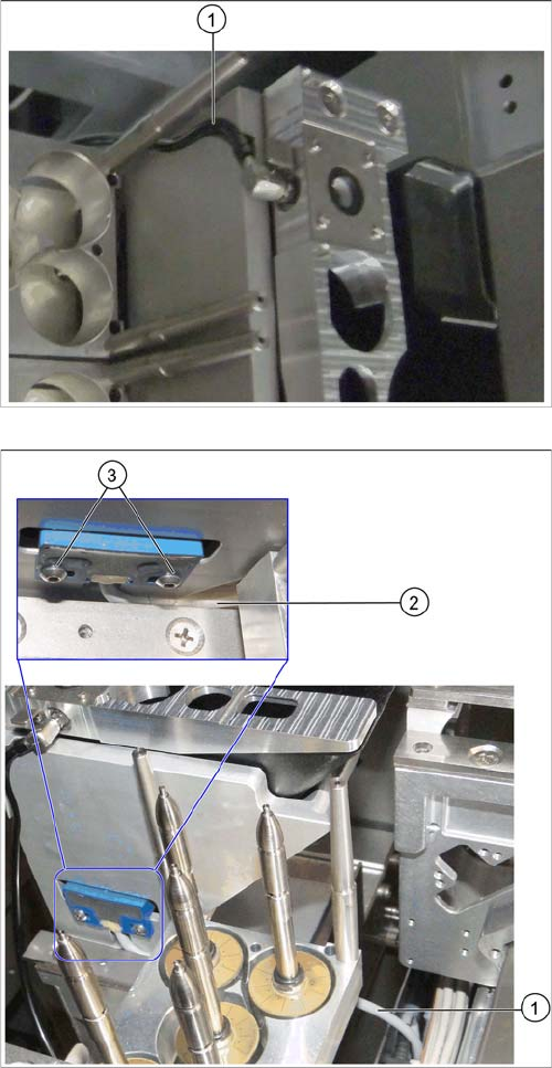
► Insert the nozzle station into the basic assembly.
► Run the compressed air line through the groove on
the basic assembly (1) and connect it to the nozzle
station.
► Insert the reject bin from the first into the second row.
► In the first row, fit the coding sheet into place.
► Run the sensor cable between the W5 magazine sup-
port and the nozzle station container (1) and (2).
Make sure that the cable is not bent or pinched.
► Install the reject bin sensor to the basic assembly for
the second row of nozzle changers and fix it into
place with the screws you removed earlier (3).
Installation
X3 S / X4 S - Installing the NC Row 2 3.2.4 Location 2 with WPC and Twin/CPP
98 NC Row 2 - NC in Front of MTC 2/WPC PPW 2te Reihe - PPW vor MTC 2/WPC
3.2.4.7
3.2.4.7 Connecting the NC Row 2
Connecting the NC Row 2
► Set the jumpers (if present) on the nozzle changers (see "4.1.1 Jumpers on the Nozzle Changer"
[ ➙ 101]).
Data cable for NC 2 and SPS
Labeled data cables have been prepared in the machine
for the various configurations of nozzle changers with and
without Smart Pin Support (SPS).
▪ X1*a (NC 1)
▪ X1*b (SPS (1) or NC 2 (without SPS))
▪ X1*c (NC 2 with SPS)
▪ X1*d (SPS2)
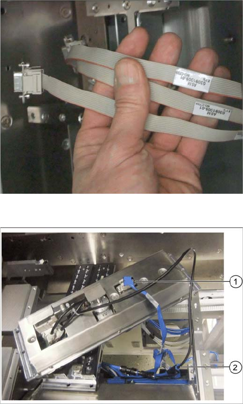
Underside of NC 2 with data cable and compressed air
line (example of X4i S)
► Connect the relevant data cable to the underside of
the NC 2 (1).
► Connect the compressed air line to the free connec-
tion on the Y coupling (2).