BM料架治具使用手册.pdf - 第23页
MOTOR 72 The center of the hole indicates the wheel position of the motor−operated feeder for 72 mm. Example of feeder type indication Feeder Inspection Unit 2.3 Gauge Jig Specifications 2.3−2 DX1OEC−12−320−A0 • The cent…
2.3 Gauge Jig Specifications
Feeder Inspection Unit
2.3−1
DX1OEC−12−320−A0
2.3 Gauge Jig Specifications
DX1OEC−12−320−A0
Sentence No.
=REMARKS=
• Be sure not loosen or remove the set screws of the stopper, block, guide pin, clamp claw and plate.
Otherwise, accuracy of the gauge jig cannot be ensured.
• Do not touch the plate. This can deform the plate.
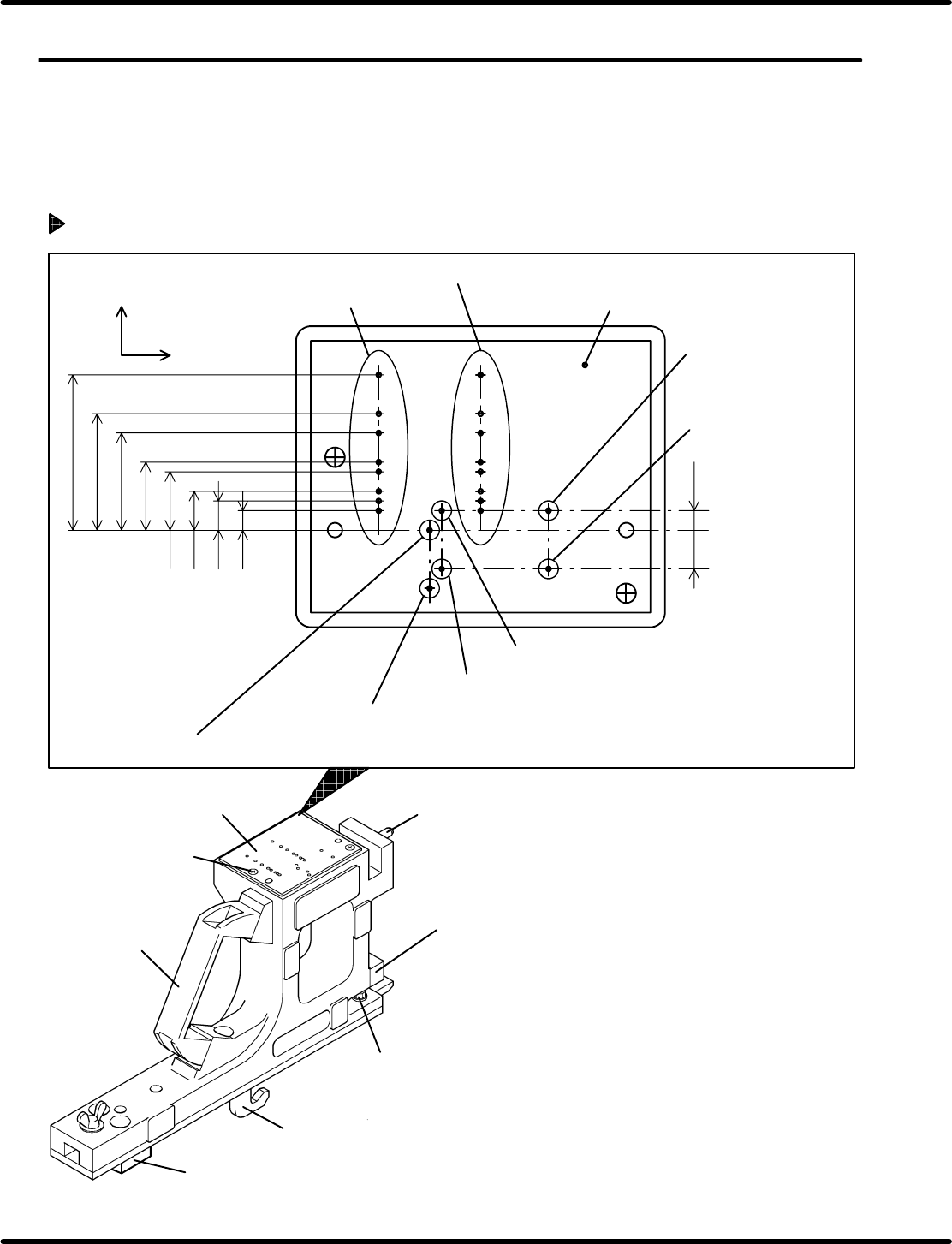
Arrangement of Wheel Positions and Pickup Positions of Feeders
72
56
44
32
16
8
72
56
44
32
24
16
12
V
MOTOR AIR
V
W
24
12
0603
8
W
34.2
26.2
20.2
14.2
11.5
7.5
5.5
3.5
10.75
Plate
Pneumatic feeder
X direction
(Width direction)
Y direction
(Feed direction)
Motorized feeder
Pneumatic double feeder
(R side)
Pneumatic double feeder
(L side)
V
R
: Pickup position (Motorized feeder, pneumatic feeder, double feeders; R side)
V
L
: Pickup position (Double feeder, L side)
Pneumatic double feeder
for 0603 (R side)
Pneumatic double feeder for 0603 (L side)
Guide pin
Plate
Gauge jig
Set screw
of plate
Block
Clamp claw
Guide pin
Stopper
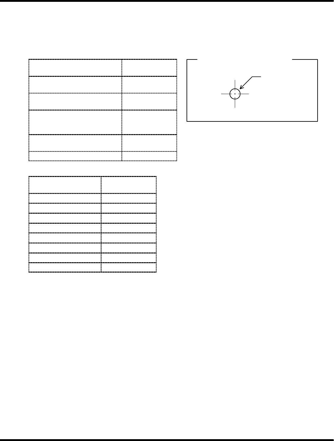
MOTOR
72
The center of the
hole indicates the
wheel position of
the motor−operated
feeder for 72 mm.
Example of feeder type indication
Feeder Inspection Unit
2.3 Gauge Jig Specifications
2.3−2
DX1OEC−12−320−A0
• The center of a hole in the plate refers to the wheel and pickup positions of the respective feeders.
• A number (8, 12, 16, 24, 32, 44, 56, 72) next to a hole is the tape width of the feeder concerned (feeder
specifications).
• Letters adjacent to the wheel position hole stand for the feeder type (‘MOTOR’, ‘AIR’,
‘W’
0603
, ‘W’).
• Pickup position is marked with ‘V’ next to a hole.
Feeder type
Indication on the
plate
Pneumatic feeder
(Single feeder)
AIR
Motorized feeder
(Double feeder)
MOTOR
Pneumatic feeder
(Double feeder)
(Other than 0603)
W
Pneumatic feeder
(Double feeder) (For 0603)
W
0603
Pickup position V
Tape width
Indication on the
plate
8 mm width 8
12 mm width 12
16 mm width 16
24 mm width 24
32 mm width 32
44 mm width 44
56 mm width 56
72 mm width 72
2.4 Dimension Gauges for OHP
Feeder Inspection Unit
2.4−1
DX1OEC−12−330−A0
2.4 Dimension Gauges for OHP
DX1OEC−12−330−A0
Sentence No.
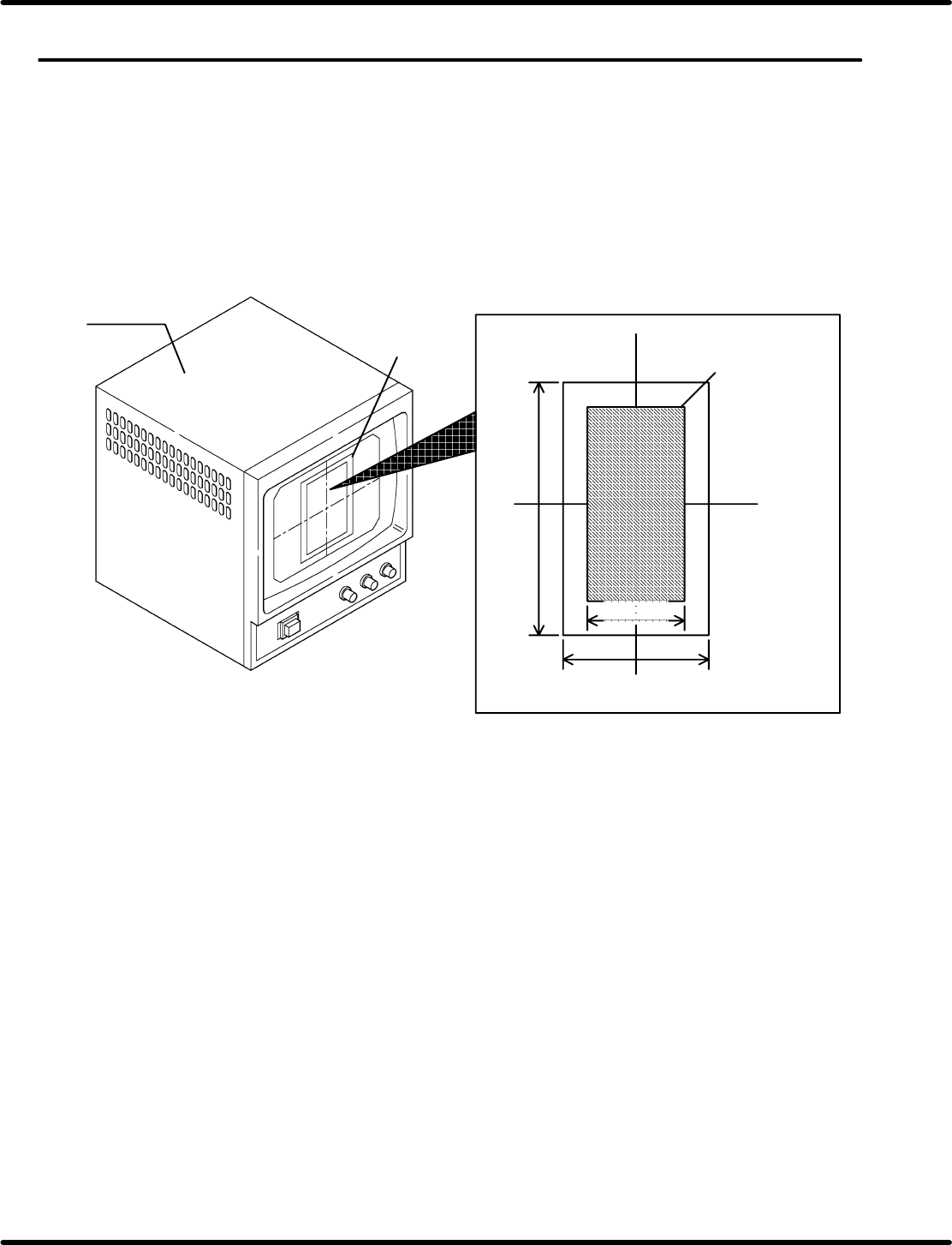
2.4.1 Overview
The dimension gauges are for attaching a transparent film indicating the tolerance range for adjustment
of the feed wheel to the monitor so as to make OK/NG judgment easily.
• The gauges described in ‘2.4.2’ show the tolerance range for adjustment of the 9−inch monitor (Option).
• When using an optional 9−inch monitor, photocopy it normally (1/1).
• If the monitor size is different, it is required to enlarge or reduce the dimension gauge according to the
monitor size.
1mm
Monitor
Dimension
gauge
Wheel outer size frame
Tolerance range in X direction
Tolerance range in Y direction
=HINT=
When using the gauge with other sized monitor, the outer width of the feed wheel will be 1 mm
(1.2 mm only for 0603 double feeder). So enlarge or reduce it according to the outer width (1 mm
on the display) of the feed wheel on the monitor.