BM料架治具使用手册.pdf - 第83页
Feeder Inspection Unit 5.2 Routine Check Item 5.2−4 DX1OEC−80−080−A0 = MEMO =
Connector
Set bolt
LED
LED
Bolt
Nameplate
Feeder side
Camera view
select lever
5.2 Routine Check Item
Feeder Inspection Unit
5.2−3
DX1OEC−80−080−A0
Checking Accuracy
Precision of the gauge jig should be checked once a year. Contact Panasonic service office.
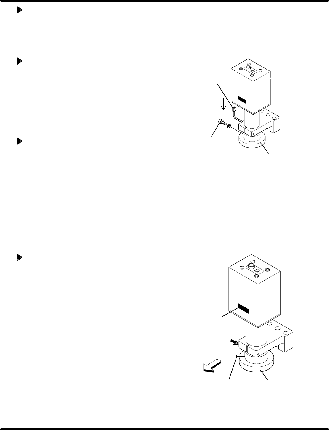
5.2.2 Replacing LED in the Camera
Replace the LED after about 10,000 hours of use and if clear view cannot be obtained.
Removing Procedure
1. Disconnect the connector.
2. Remove the set bolt at the LED.
3. Pull out the LED downward.
Attaching Procedure
Mount a new LED in reverse order to the removing.
(Be sure to install the LED in proper orientation.)
=REFERENCE=
LED is a consumable part.
Name: LED
Part No.: N940Q3A03706
Replacing the Camera (Reference)
1. Detach the LED. (Refer to ‘" Removing Procedure’
above.)
2. Loosen the bolt securing the camera.
3. Withdraw the camera upward.
4. Remove the LED on a new camera and attach it with the
nameplate faced on the feeder side.
5. Reattach the LED in the reverse order of removal.
6. Make adjustment by referring to ‘5.1.1 " Adjusting the
Camera Position’.

Feeder Inspection Unit
5.2 Routine Check Item
5.2−4
DX1OEC−80−080−A0
= MEMO =
5.3 Lubrication
Feeder Inspection Unit
5.3−1
DX1OEC−80−140−C0
5.3 Lubrication
DX1OEC−80−140−C0
Sentence No.
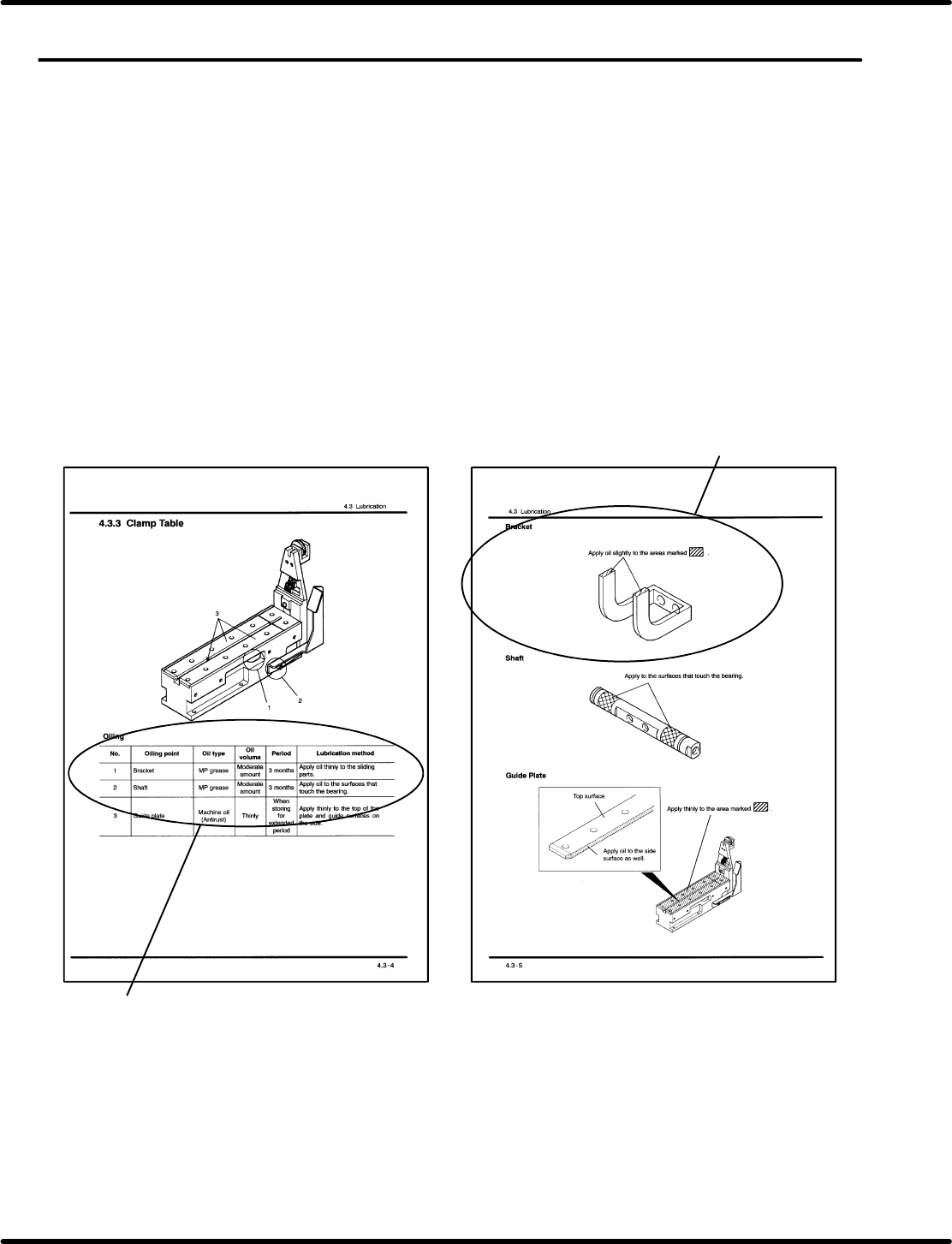
5.3.1 Guide to Lubrication Table
Configuration diagram: Presents the detailed view tape feeder in a parts list format.
Parts caulked to make a single cast are also shown.
Oiling point: Lists the parts requiring lubrication indicated in the configuration drawing, with
necessary information such as oil type, oil volume and period of oiling.
Description: Illustrates the details of parts requiring lubrication.
=REMARKS=
Do not disassemble the feeder adjust unit for oiling because each part of it has been adjusted.
Be sure to observe the instructions when replacing the unit.
Detailed explanation
Oiling point
Feeder Inspection Unit Feeder Inspection Unit